
At long last, we can now begin the fun part of this whole process.
For today’s session, we’re going to build a helmet. The easier thing to make would be a sword or some other kind of weapon, but fiddling with an object that requires skinning data (more on that later) will help cover more ground. By the end of this, you will hopefully have a firm enough grasp on the process to be able to tackle other types of objects with relative ease.
Buckle up folks, it’s going to be a long one. With that said; as long and complicated as this may seem, the actual model itself is really simple, and took no longer than half an hour to make the base mesh. Which is to say; it’s less complicated than it looks, even if the first time around may seem intimidating.
Warming up the Forge
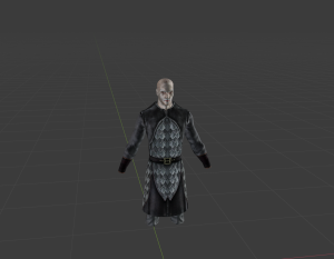
As covered in the last post, the “scene” in Blender should consist of a suitable model to measure your size, proportions and placements off of. Note that making a perfect shape for helmets to fit on all heads is a bit of an uphill battle, especially when it comes to elves and half-orcs, due to a lack of universal proportions across the board. We can, however, do our best to approximate. Usually, the best base to use in this case is either a Tiefling or Human male head.
WHY HUMAN MALES?
The proportions used human/ tiefling males are normally the same used on Genasi, Yuanti, Aasimar, and an assortment of other community made races. They also tend to not deviate too badly from their female counterparts, which normally just require a small bit of resizing to work. Ergo, if you’ve made the right shape and size for a human male, it -should- fit on most other head types just fine.
The helmet in question will be a fairly simple one: the Guvner Bailiff’s helmet.
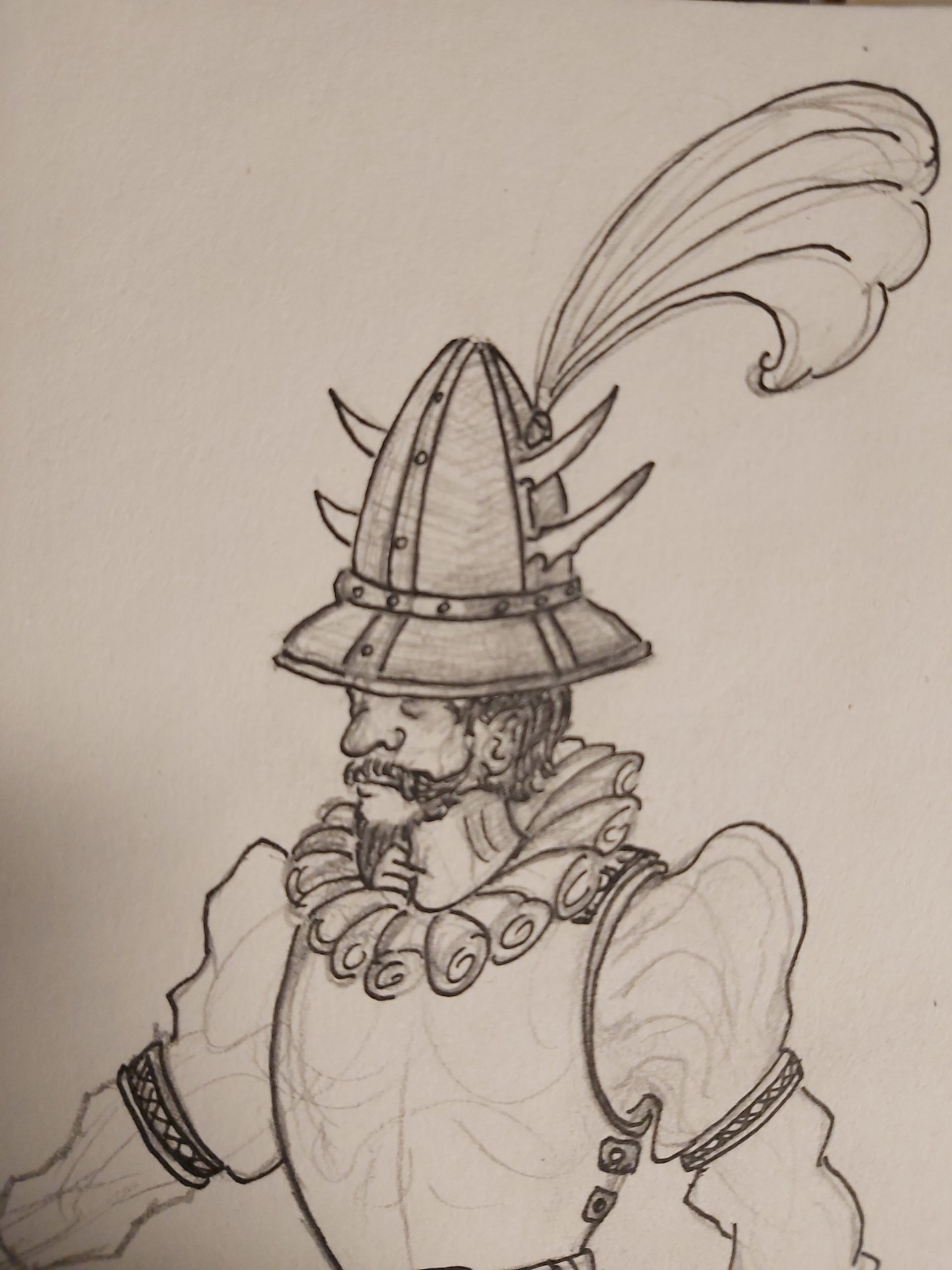
Yes, it’s a weird one, and yes, it’s foppish by design. It will be our subject for a few reasons:
- It will have fairly simple geometry.
- The plume will give us a chance to mess with some transparency effects.
- The Fraternity of Order needs FABULOUS guards.
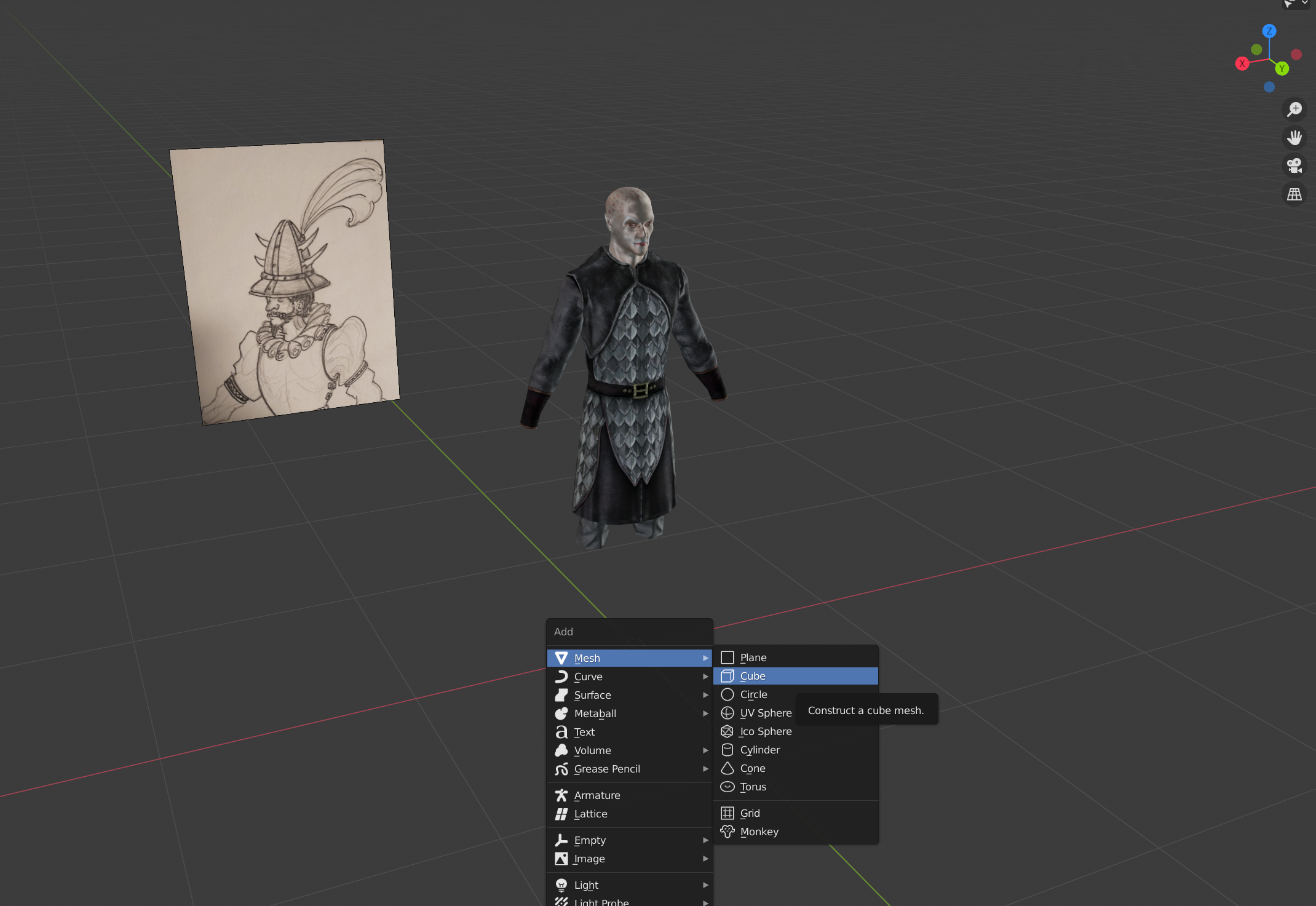
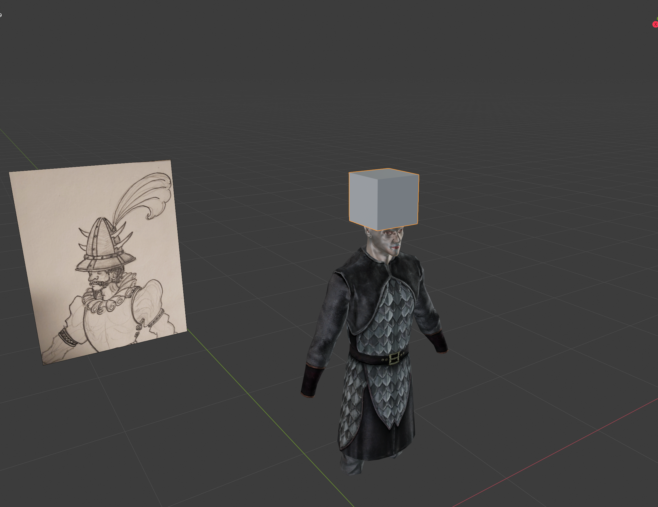
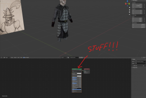
Throughout the modelling process for any object, you will likely need to keep referencing a photo or concept sketch of your subject. Sometimes it helps to have that reference in your modelling scene itself, which can be done by adding in a reference object. To do so, press the [Shift] and [A] keys to bring up the Add Menu. From there, mouse over the “Image” section, and click on “Reference”.
What a mesh!
Once you have your reference set (and once you’ve fixed it’s orientation to whatever suits you), we can begin the real work.
To start with, hit [Shift]+[A] again. This time, mouse over the Mesh list, and select “Cube”.
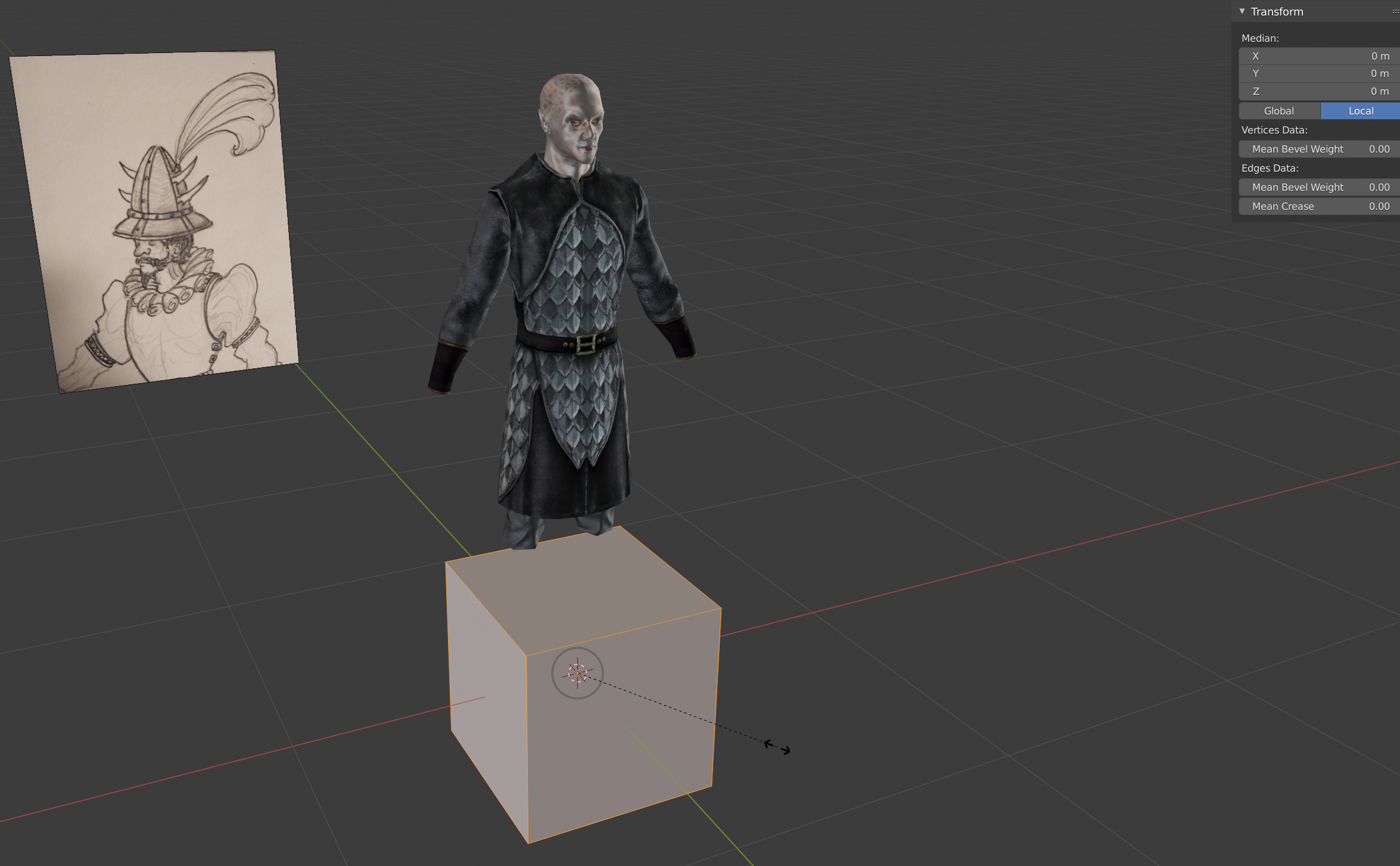
Once the cube has been created, hit the [Tab] key to enter “Edit Mode”.
On OBJECT and EDIT Mode
In Blender, there are several modes in which you interact with the things in your scene. OBJECT MODE is more or less the default, where you simply move the item in question from place to place (or rotate and scale it). Essentially, it’s where you set the stage
EDIT MODE is like the workshop, where you actually modify a 3D mesh’s wire frame/ shape, UV Unwrap, and other core properties.
Once you’re in Edit Mode, notice how you can’t select anything besides parts of your cube. This is because Edit Mode only pertains to the selected objects.
While in Edit Mode, Press the [A] key to select all parts of the cube. Then, tap the [S] key to scale your cube. Once it’s small enough to no longer encompass the whole body, left click to confirm. This will disengage the scaling operation, and bring up a confirmation window on the left. You can make further adjustments to the total resize here, before confirming with another left click.
NOTE ON THE TRANSFORM OPERATION
Transforms- be it move, scale or rotate- can be done in Object or Edit Mode. However, the actual action occurring differs in each. In Object mode, transforms are done as a shift in the relationship between the object and the whole world. In Edit Mode, changes are made in regards to parts of the object and it’s own zero point, or pivot.
Next (and while still having all parts of the cube selected), press [G] to select the move tool. This will make everything selected follow your mouse. All we want is to shift the box up the head. To make sure the cube doesn’t move to the back or side, lock the transform axis by tapping the [Z] key.
Splits
We have one last transform to make before we’re ready to start making this hat less of a box.
With all sides of the cube selected, hit [R] to rotate it, and once again, press [Z] to lock the transformation’s axis. You can also hold down the [CTRL] key to make the rotation snap to increments, though it doesn’t matter here. Left click anywhere to bring up the confirmation window. Once up, select the text box next to “Angle”, and type in “45” (or -45).
TIP
You can directly set the transformation value while rotating, by just typing “45” after locking the axis in this case.
Time for the first incision!
First, make sure your selection mode is set to Vertex. 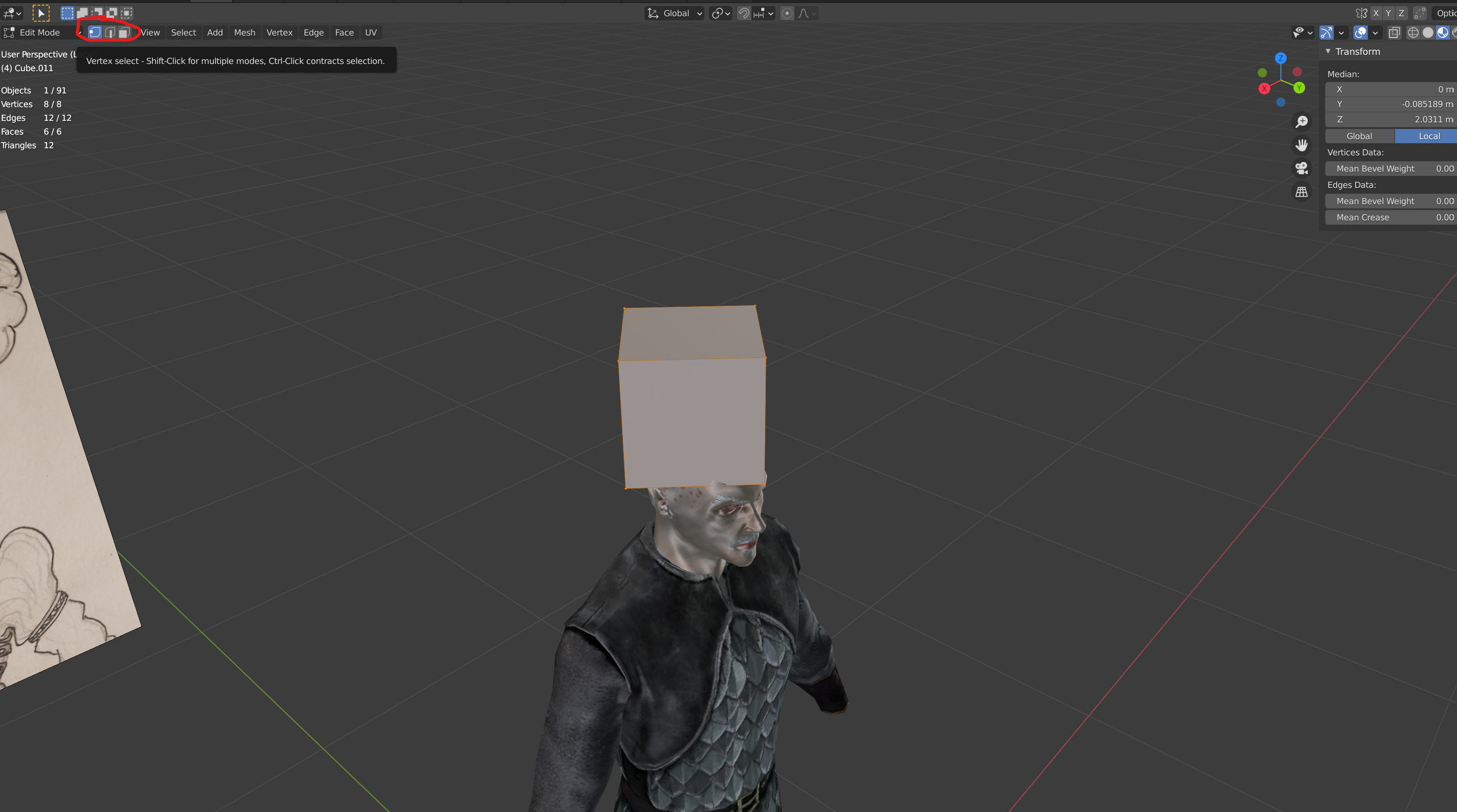 This can be done either by clicking on the icon in the screenshot, or by hitting [1] on your keyboard.
VERTEX, EDGE and FACE selection modes can be switched on the fly. Think of them as weapons in a game, accessed by hitting 1, 2 and 3, respectively.
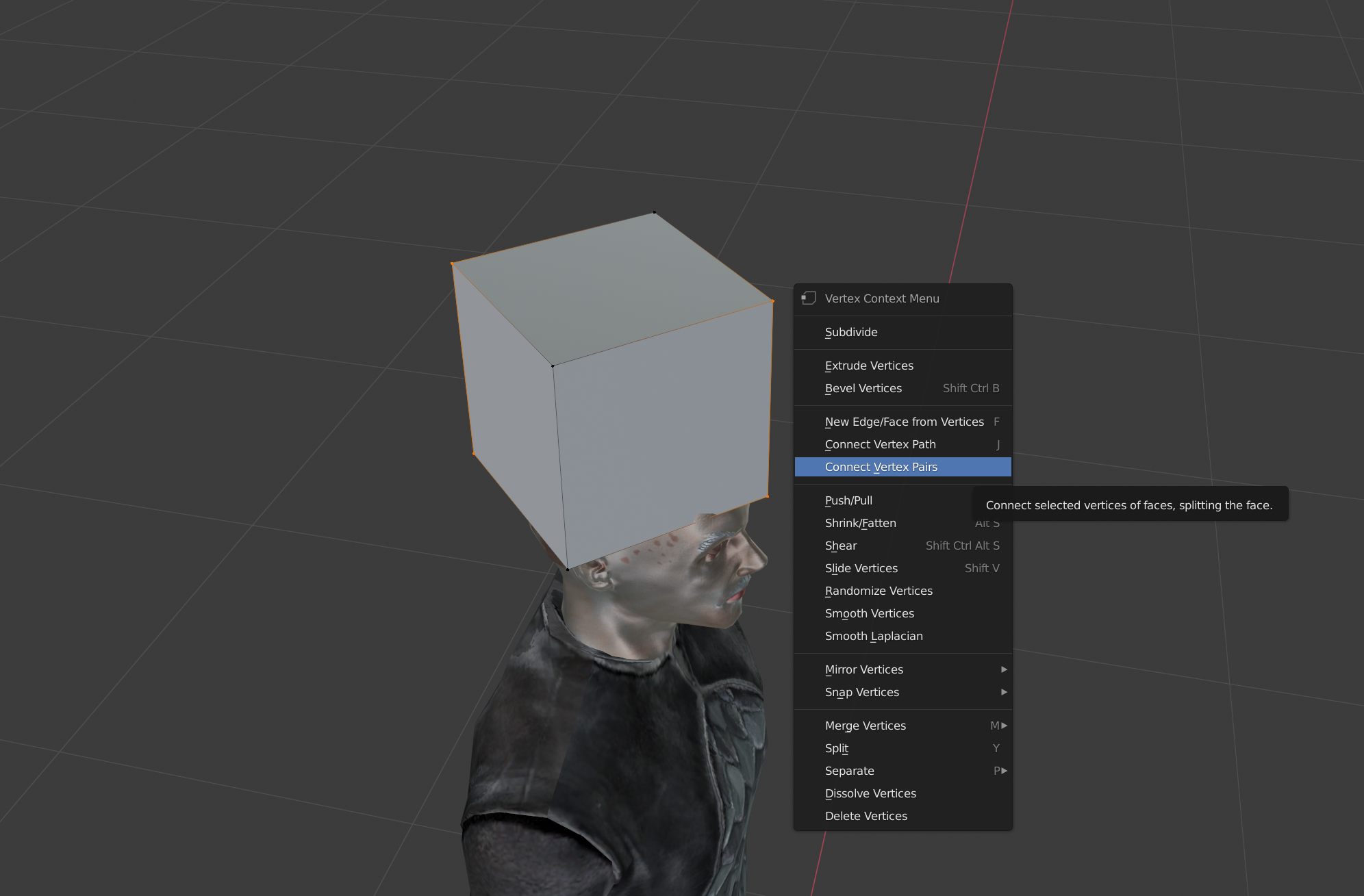
Once in Vertex selection mode, select the top two vertex’s running along the Y axis of the cube. Then select the same on the bottom. Next, click the right mouse button to bring up the Vertex Context menu. Click on “Connect Vertex Pairs.”, as indicated in the “Rotate and Connect” image.
Congratulations, you’ve made your first modification to the base cube’s geometry!
The next step requires us to be in Edge selection mode, so switch over by hitting [2]. Select the two edges you just made, and click the right mouse button. Notice that the Context menu is now different, as we are no longer in Vertex Mode. If you can’t notice anything having happened beyond the confirmation window coming up, don’t worry. Just switch back to Vertex mode, in which you should see a new point having formed in the middle of the edge.
Select both the top and bottom new vertex’s, as well as the two points on the X axis. Once more, bring up the context menu and select “Connect Vertex Pairs”. 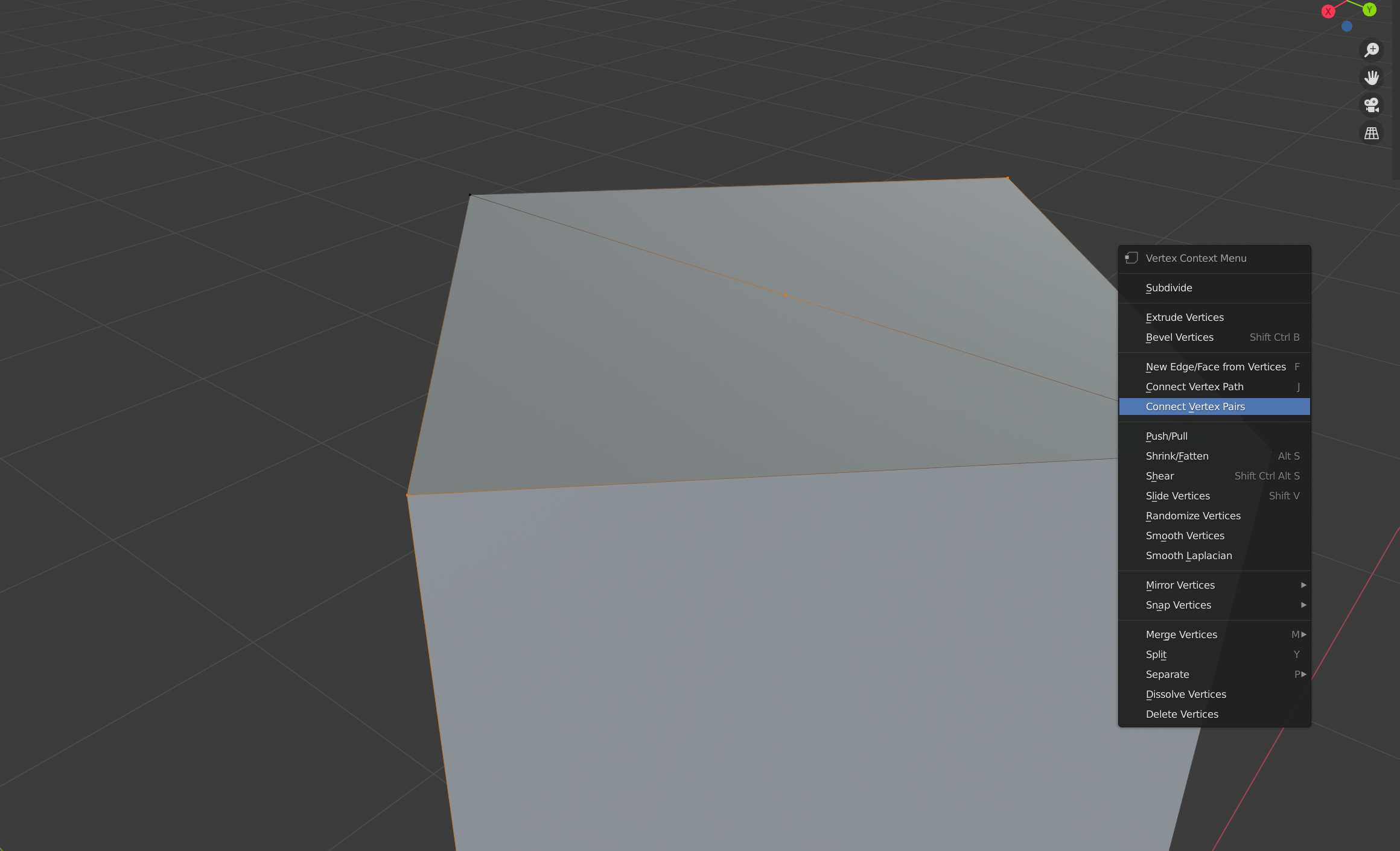
Now, it’s time for some more dramatic changes.
Rounding Off
First, make sure you’re back to Edge selection mode. Then, while holding down the [Shift] and [Alt] keys, left click on an edge running down the middle of both the X and Y axis, as indicated to the next image.
WHY THE [ALT]+[Shift]?
This lets you select Edge Loops, which is handy for modifying large paths.
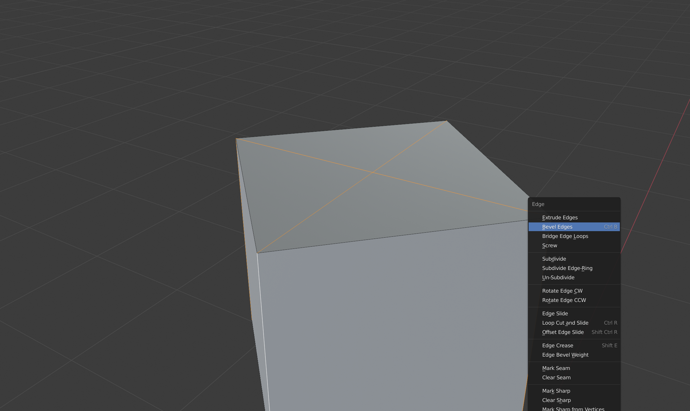
Also as shown, bring up the Context menu, and select “Bevel Loops”.
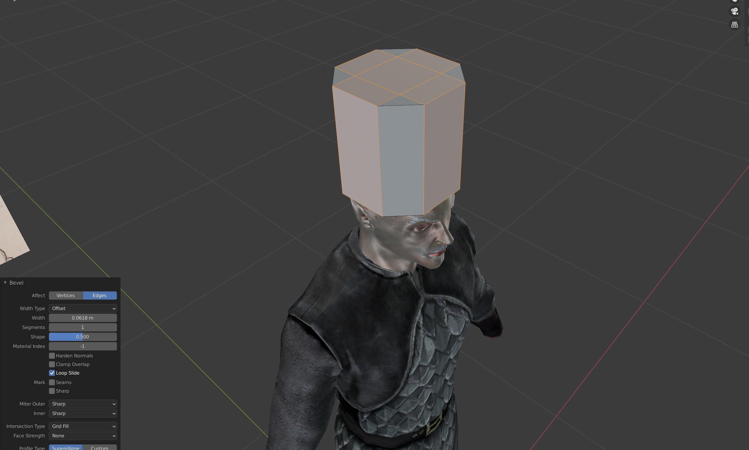
As you can see, the Bevel function essentially pulls apart your edges and creates a new “face” (polygon) between the two new lines. Confirm with a left click when your shape is roughly as follows.
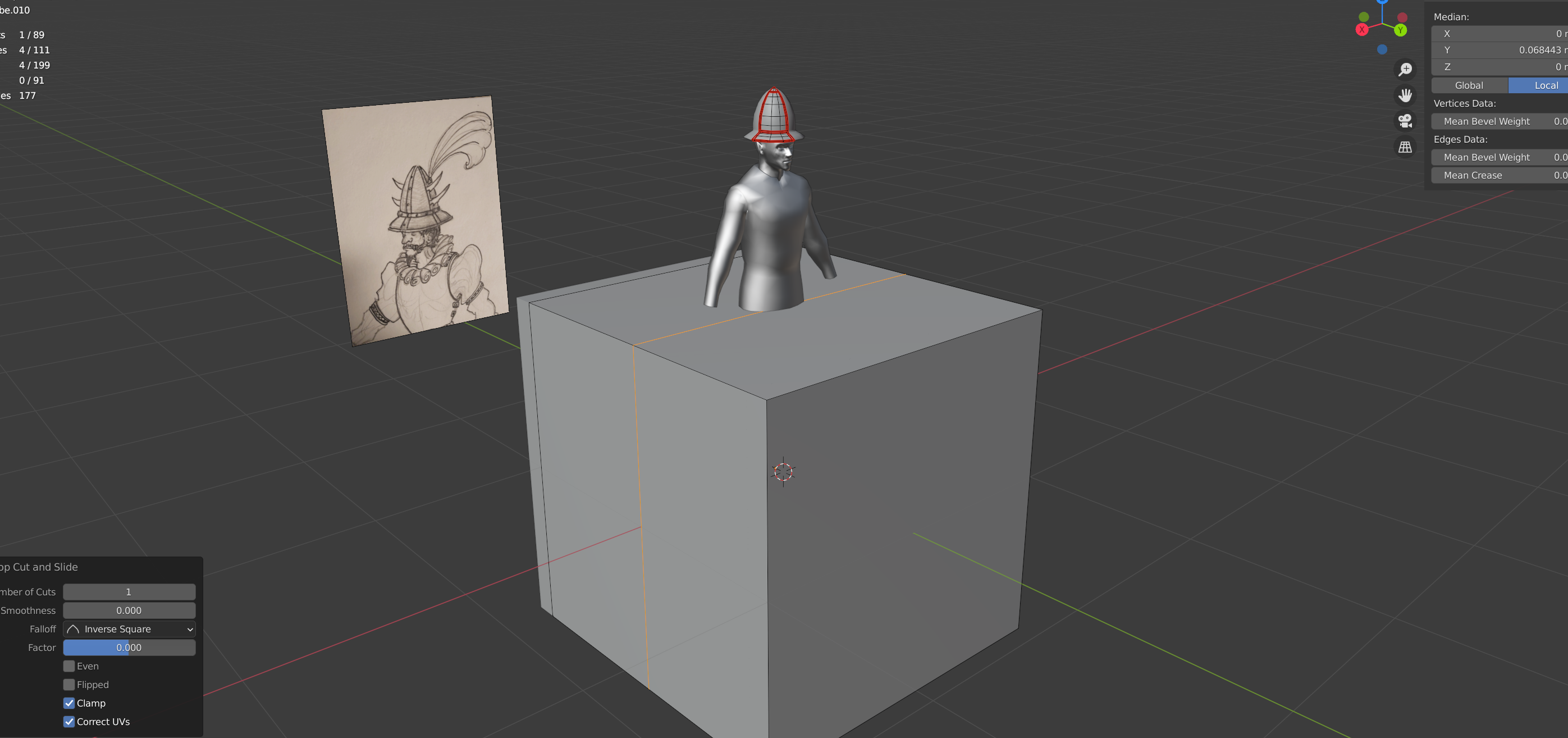
We need to create a couple more edge loops next, but instead of pulling them out of existing lines, we need entirely new divisions.Specifically, we need to split the middles of the Y and X axis. There are multiple ways to do this, but for now, let’s use the shortcuts.
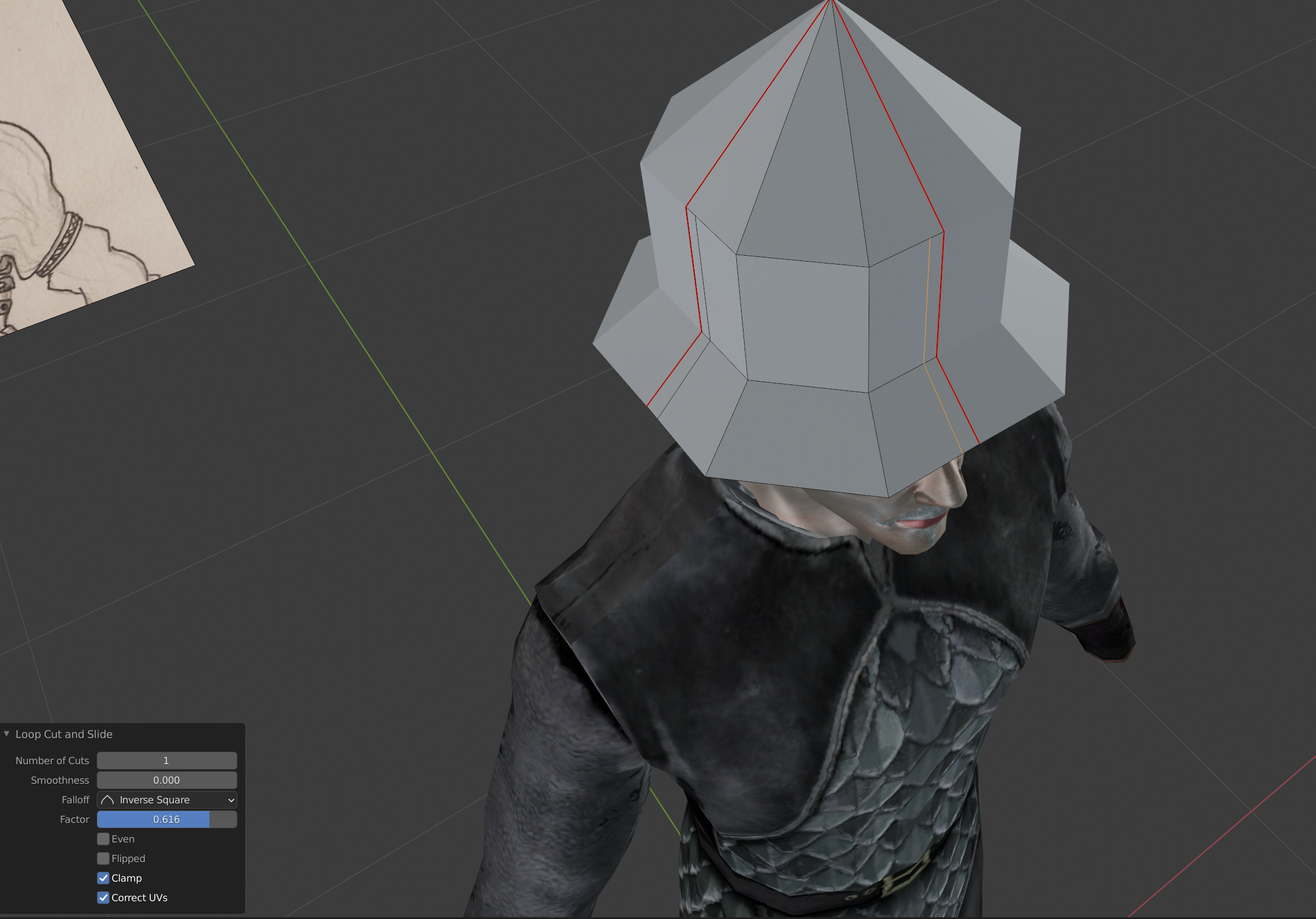
Hit [Ctrl] + [R] on your keyboard, and mouse over the top left or right of the mesh. You’ll see a yellow loop forming, which is a preview of where your cuts will land.
Once you get the loop as shown in the image, left click.
Wait a minute… that didn’t confirm the action this time! And worse yet, the loop is moving with the mouse! That’s because we have two ways of confirming the action here. If you left click after moving the edge around, the confirmation will be to make the cut at where it was visually left off. However, right clicking will snap the transform back to its initial preview point. It’s the latter that we want here, as this loop needs to be 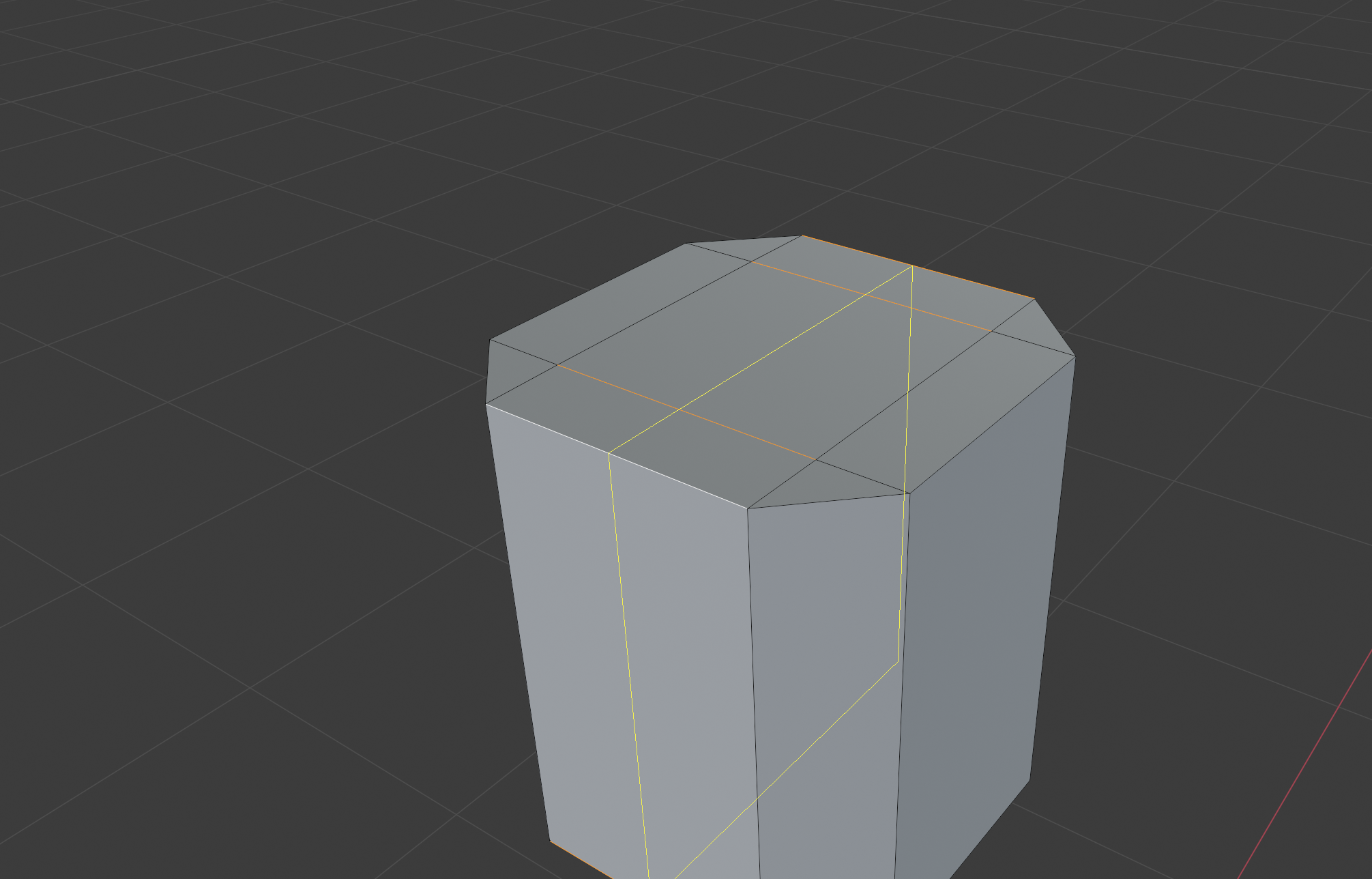 a central dividing line.
When you’ve confirmed the loop, do another one for the Y axis.
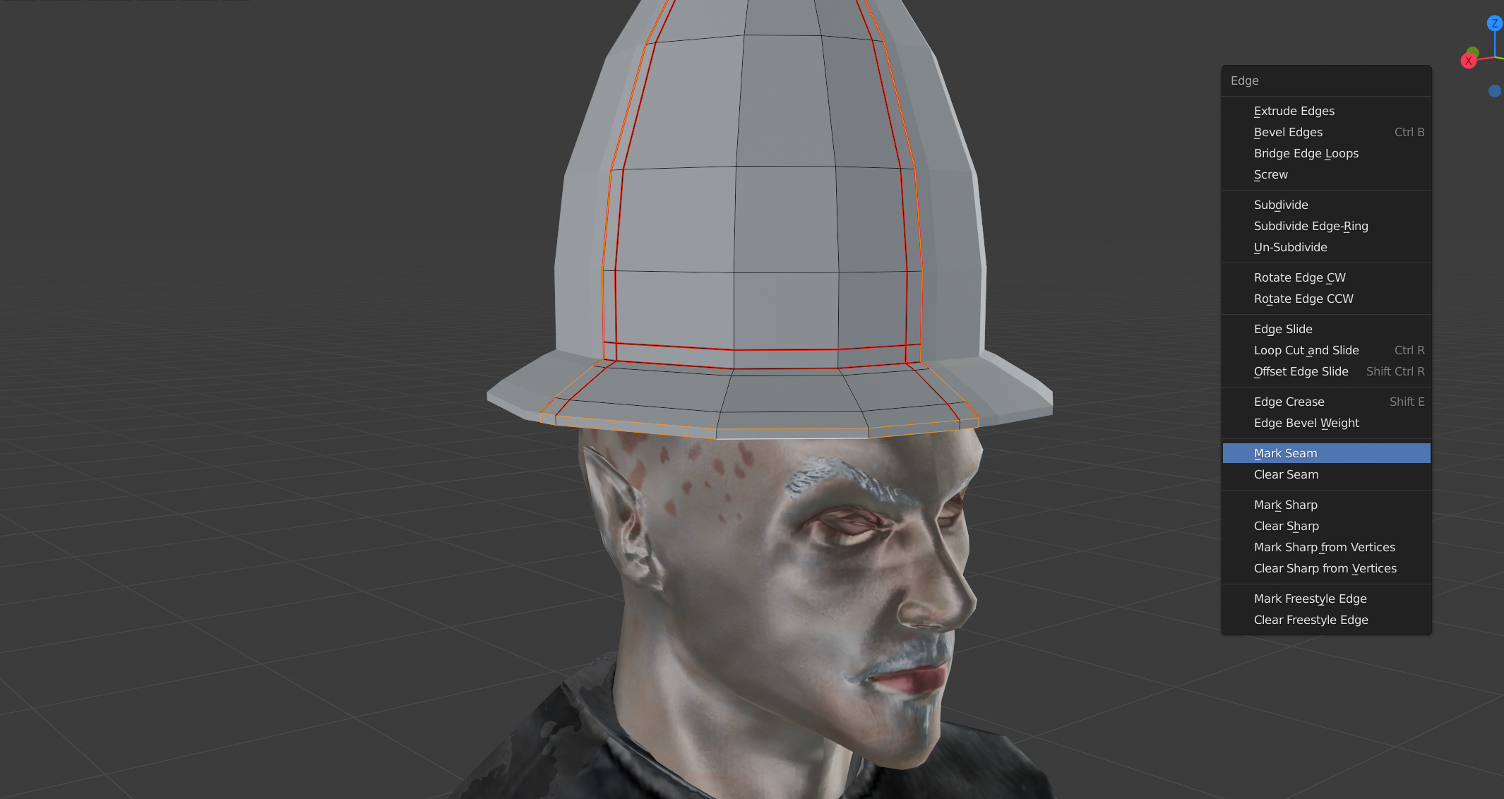
Time for another loop selection. Using the previously noted method, select the two new loops, and from the context menu, select “Mark Seam”.
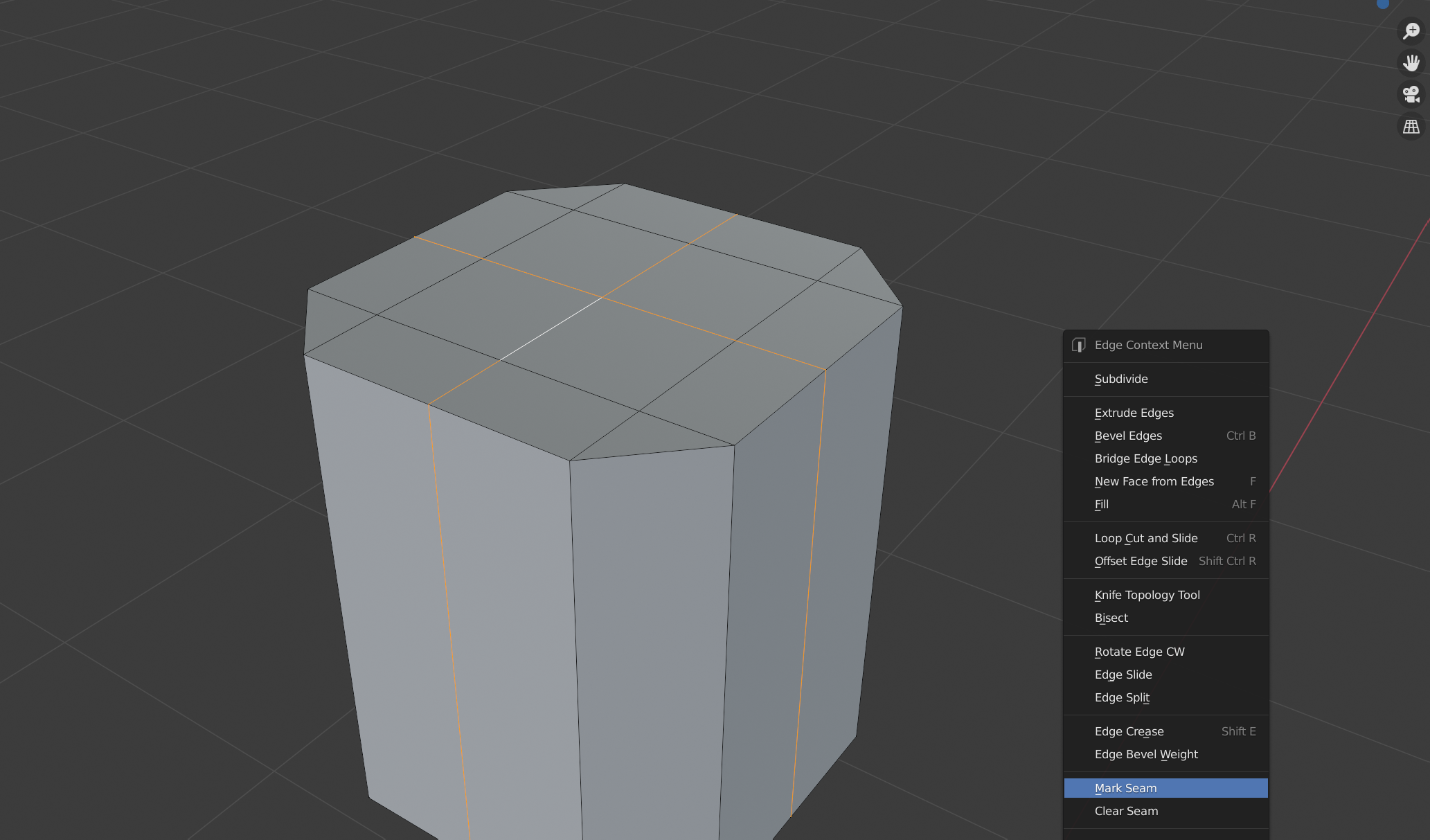
You should now see both loops changing color, specifically turning red. They are now, as the title suggests, seam lines, which mark out what’s called “islands” on the mesh. Islands are important for a couple of things;
- They can make selecting groups of polygons easier.
- They are crucial when it comes to making the UV unwrap of an object, which we’ll cover when we get to that part.
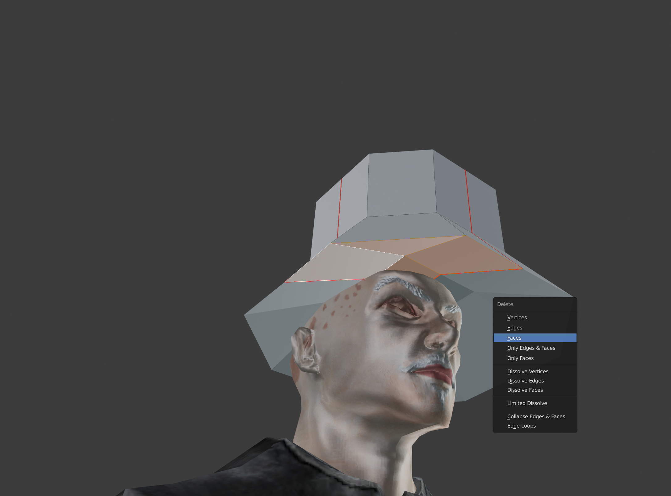
The first point is the one we need to be concerned with now. First; switch to Face selection mode ( [3] on the keyboard), and select the indicated polygons. 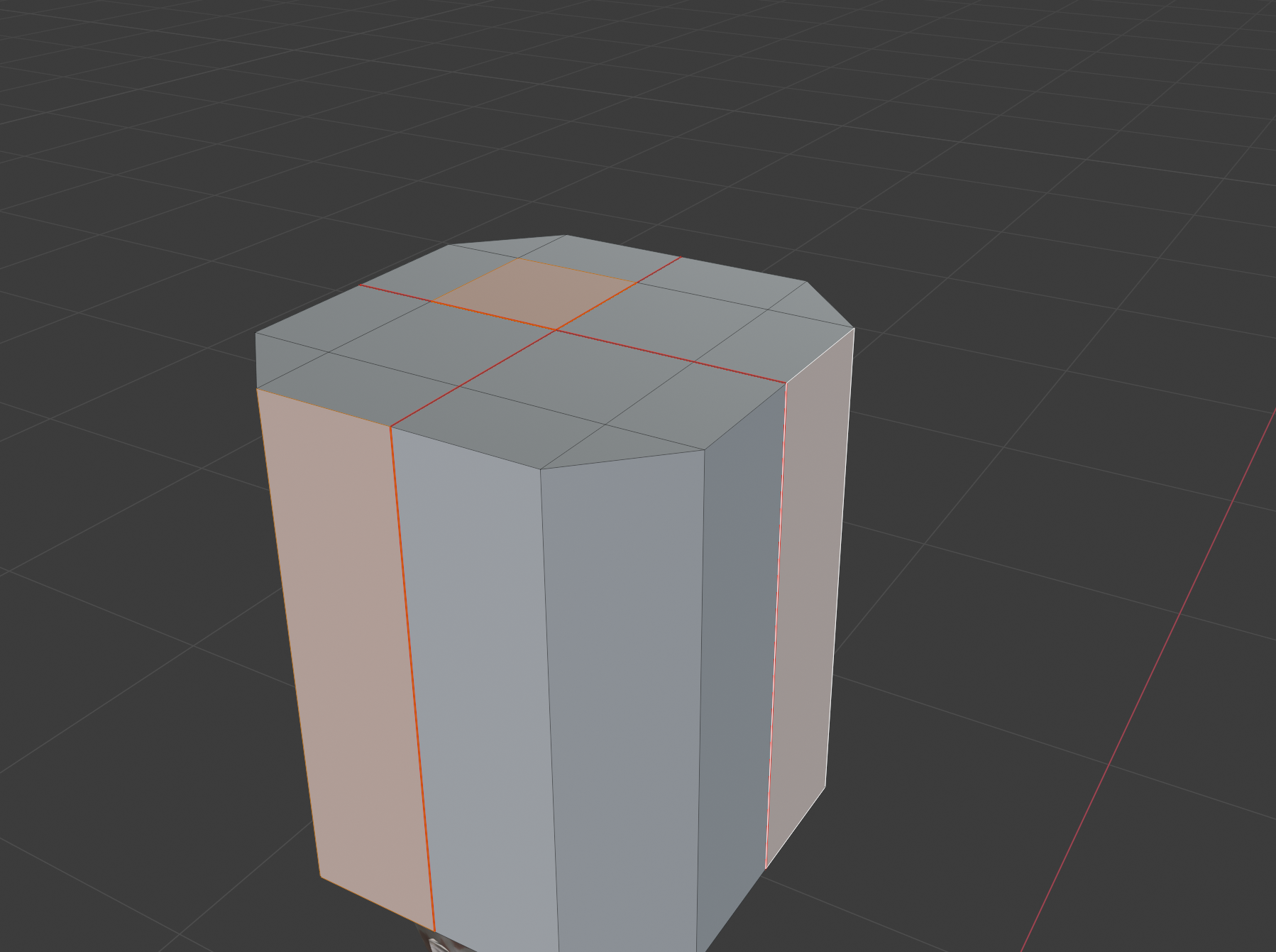 Then, press [Ctrl] + [L] on the keyboard.
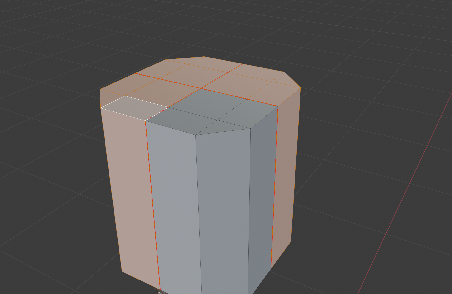
As you can see, you’ve managed to select each quadrant of the object, without needing to go in manually. Now, you may be wondering, “why did we just do that?”.
Destruction, of course!
Press the [X] key, to bring up the Delete menu, and from there, select “Faces”.
Still wondering “Why did we just do that”? It’s to save ourselves a lot of work as we go forward. See, a lot of helmets will end up being quite symmetrical. Furthermore, this particular one is fairly uniform in all of its angles, which means we really don’t need to manually shape every corner of it. So instead, we’ll just concern ourselves with a single quadrant.
Still, we do need to see how the overall shape will pan out, don’t we? That’s where the Mirror Modifier comes in.
Insert lame “Mirror Mirror” joke here
First, a very brief and simplified summary of modifiers;
They essentially, as the name implies, modify an object without actually changing its properties, till they are “applied”. For those of you who have used Photoshop extensively, they can be thought of as being similar to Blending Modes for a layer. Which is to say; they change the visual output, without permanently changing the object.
In the case of our subject, the Mirror Modifier, this means that we will see reflected copies of our mesh which technically do not exist yet. In Object Mode, you’ll be able to select each reflection as part of the mesh, but in Edit Mode, you’ll notice that each reflection can’t be, nor will they even show their wire frame overlay. Of equal importance, however, is that any change you make on the original mesh surface will automatically occur in the reflection.
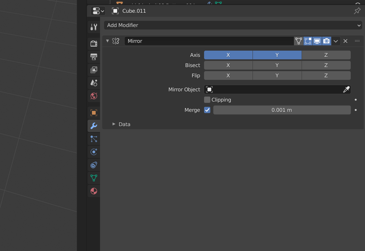
Seeing is believing, and probably a whole lot easier to follow than a wall of text, so let’s get on with it. Either while in Object or Edit mode, select the mesh (the one that we’ve been working on till now), and head over to the Modifier Properties tab (the blue wrench in the screenshot).
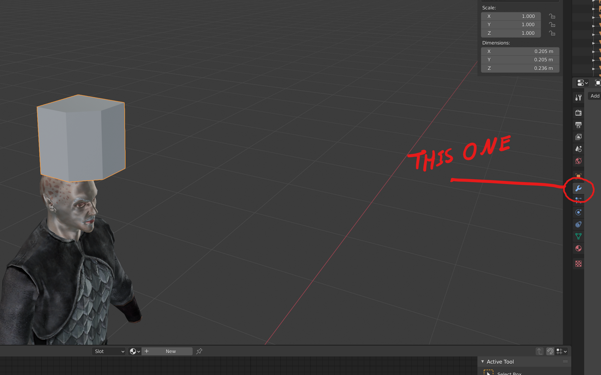
Open up the drop down menu where it says “Add Modifier”, and select “Mirror”
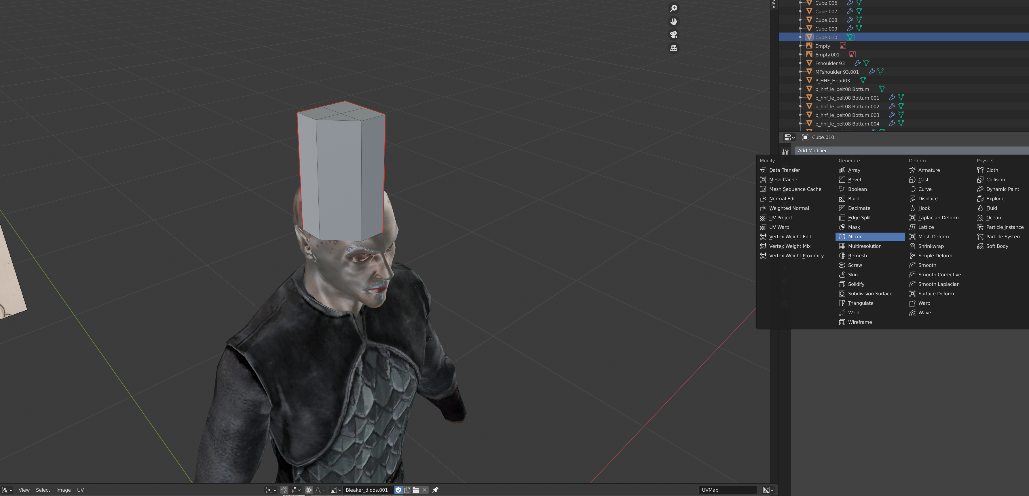
You should immediately see a reflection of your mesh on its X axis. Normally this would be enough, but for this helmet, we want the other sides too. To that end, make sure both the X and Y axis are highlighted in the resulting settings.
Alignment
Before we go forward, there’s an important note to make; our seams need to remain aligned. Right now they should be fine, but as we edit and move vertices, we will need to regularly reset their positions. For the sake of making sure you’re looking at the right thing, select the edge loop as indicated in the following image.
Notice that it’s transform position – on the X axis- is 0. This is where we want this loop to remain at all times. More importantly, we want all vertices on this loop to have the same X axis position. You can do this easily by selecting the edge loop, pressing the [S] key (scale), pressing [X], and then hitting 0. This will bring all the selected vertex points in line with one another, on the X axis. After that, with the same loops selected, ensure that the X value in the Transform window (top right of the image) is set to 0.
Shape up!
Now comes the part where we really start beating this box into shape.
To start with, select the faces at the top of the mesh, and delete them. Create two edge loops ( [Ctrl]+ [R]) running horizontally, either by making one at a time, or creating one and then using the bevel function.
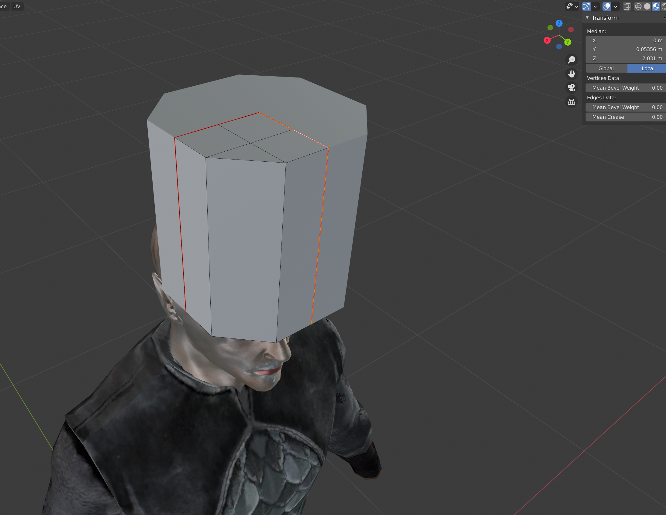
You should be looking at something along these lines:
The image is also a spoiler for your next step; collapsing the top vertices onto each other. As you’ll see, this basically takes all your selected points, and merges them into one. You’ll also note that it’s taken the top edges out of the alignment we need them in, something that can be solved by setting the new vertex’s X and Y transform to 0 each.
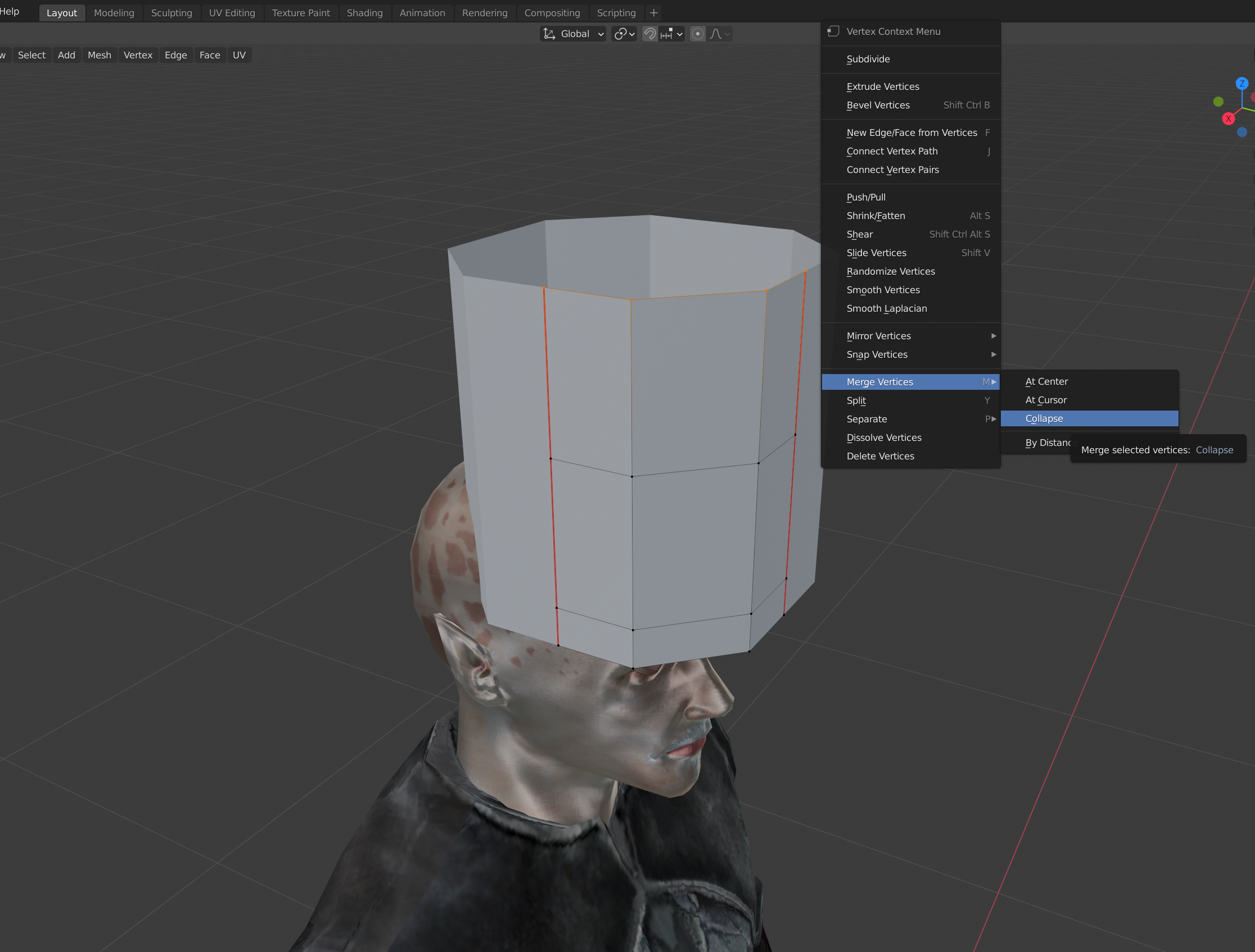
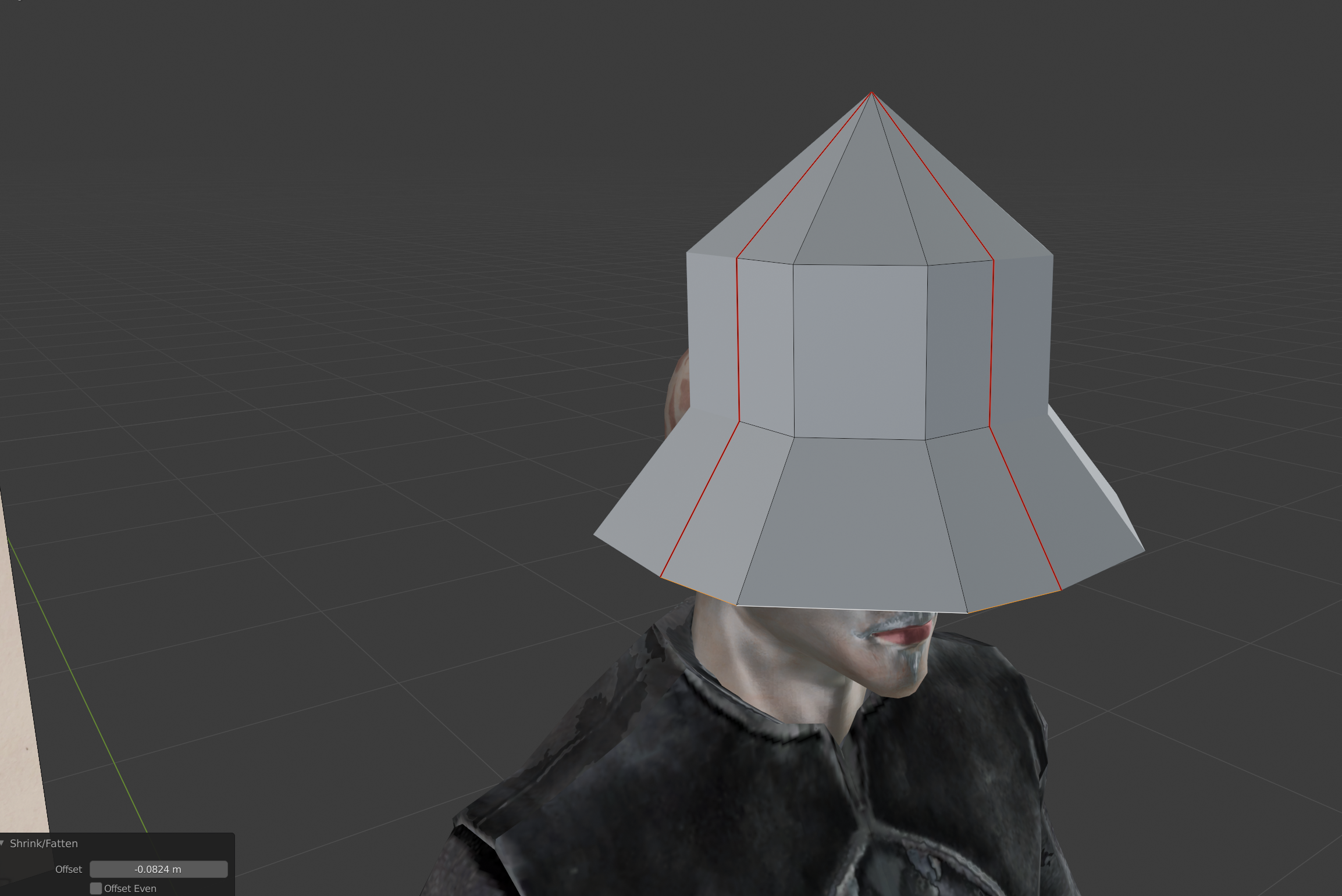
Next; select the topmost horizontal edge loop, and then engage the ‘Shrink/ Flatten’ tool either by selecting it via the icons on your left, or by pressing [Alt] + [S]. This tool will let you expand and contract the positions of each vertex/ edge without disrupting their position the way the scale tool would.
Shrink and expand it and the ring bellow till your mesh looks something like this.
Once again, double check and ensure your seams are aligned.
Loop selection selecting more than you need?
You can deselect edges you don’t want by just holding down [Shift] + Left click on the offending edge. You can also hold down [Ctrl] and drag select to exclude edges/ etc.
Before we go on, turn the camera so you’re looking at the bottom of the mesh. Select and delete all faces down there. We’ll reform them later.
Back on the front and side, make two more loop cuts, this time running vertically on the front and side. These will be used to mark out the brass rims on the helmet. Connect the topmost vertex’s to the central tip using the “Connect Vertex Pairs” function from before. Add another cut- horizontal now- above the line before the helmets brim starts.
Now it’s time to start really defining the shape of the helm. Select the topmost edge loop, and bevel it. You may need to do this a few times, and occasionally grab and shrink each loop to mold it. Don’t add too many loops though! We still need to keep our polygon count relatively low. In my final mesh, I ended up with eight loops running from top to bottom of the dome.
Remember to re-align your edge seems when you’re done shifting the loops around.
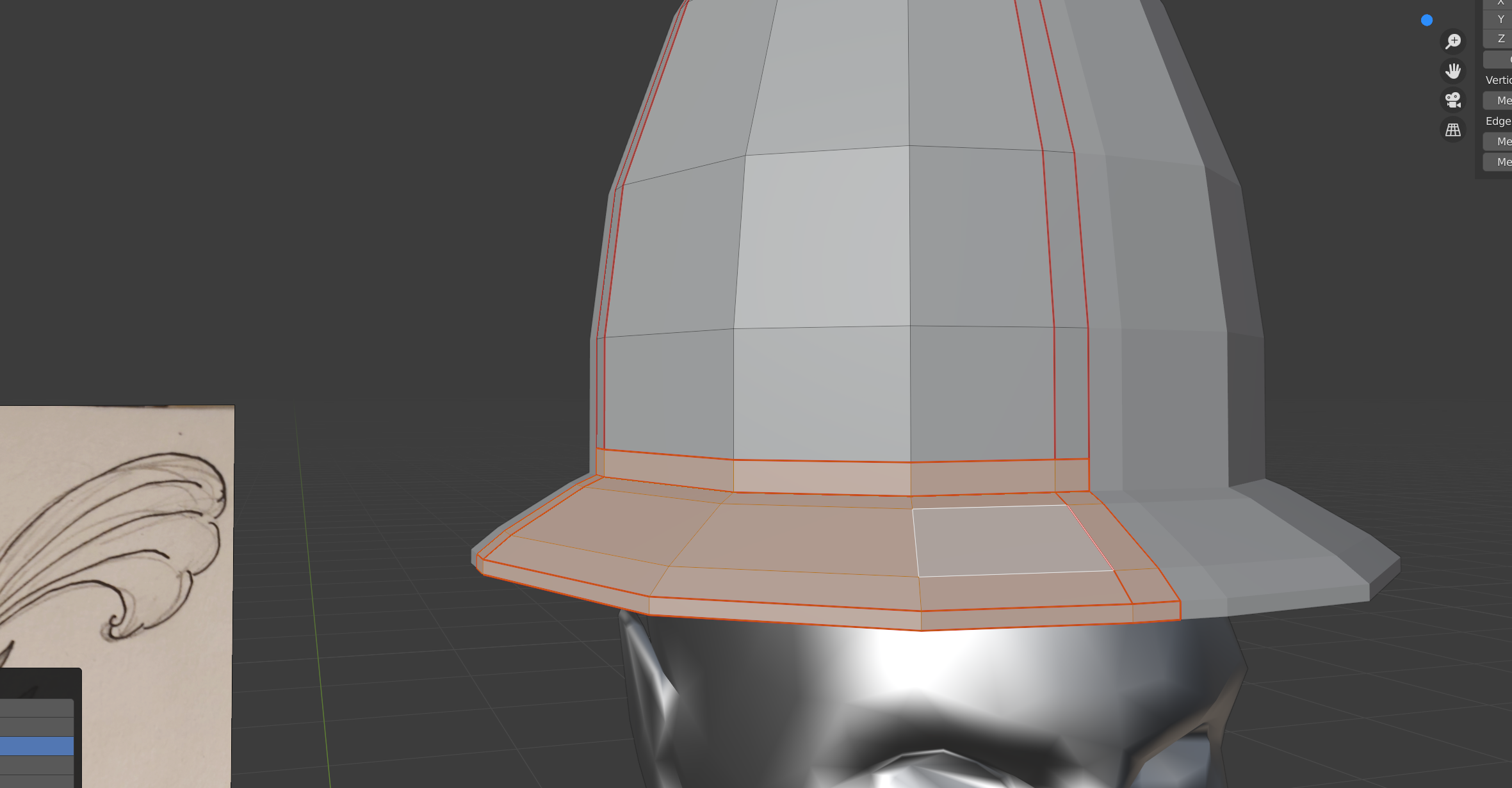
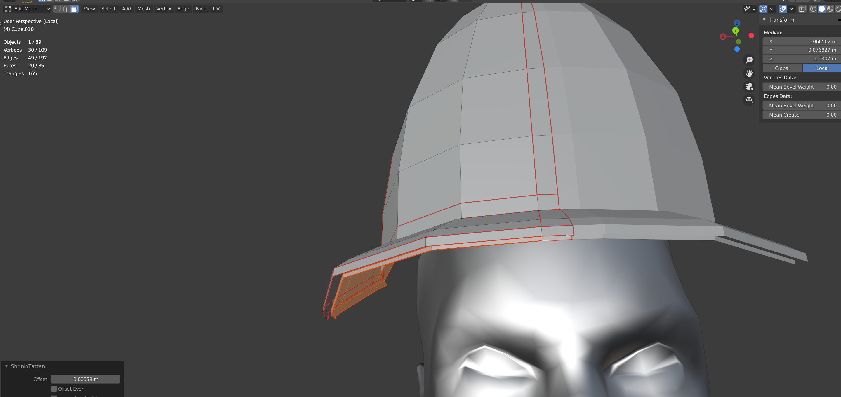
While you’re shaping up the dome, adjust the brim of the helmet accordingly. Use the [Alt] + [S] function to make it wider (or shorter if need be), and shift it along the Z axis till you have a satisfactory shape and size. When that’s sorted, select the lowest edge loop, and then press [E], followed by [Z]. [E] executes the Extrude command, which will pull out a new edge/ polygon from the selected one. Bring this new edge down (along the Z axis) just a little bit.
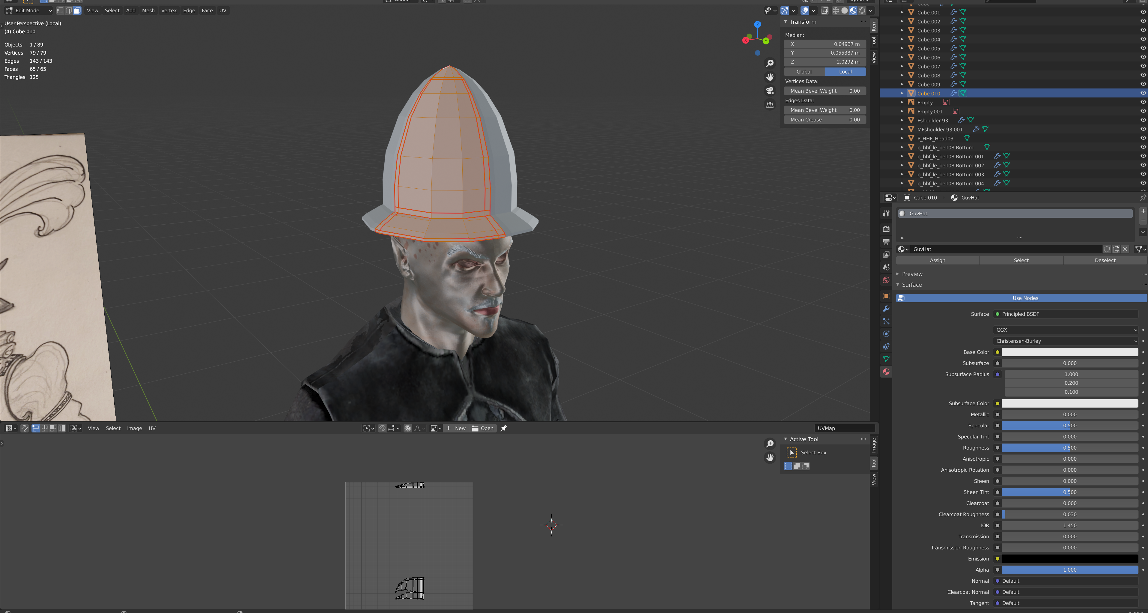
Next up; we need to mark some more seems. Unlike before, these lines won’t be used for cutting up the mesh, but instead for isolating parts of the UV Unwrap. Mark the loops shown in the next image.
The Flattening
Although we still have a fair bit more to do with the base mesh, it’s a good point to start laying out the ground work for our UV Unwrap.
UV Unwraps? What?
Refer to the first entry of this series for a primer on UV Unwraps.
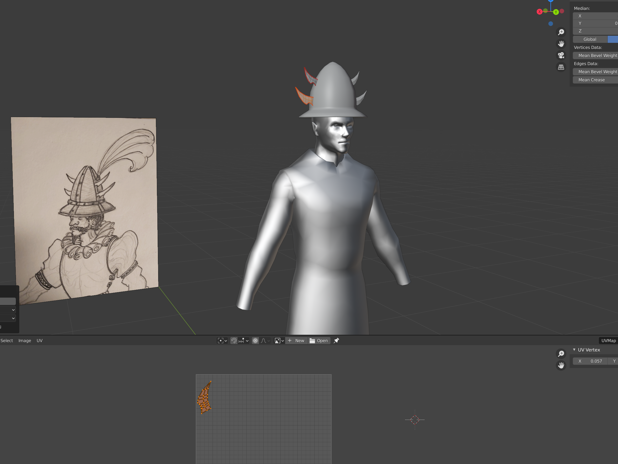
The UV Editor window is different from the Default 3D Layout/ Modelling view, and can be accessed in two ways. The first is to switch out the main screen entirely for your UV Editor, which will turn your workspace into a split between the UV view (left of the screen), and your scene view (right side).
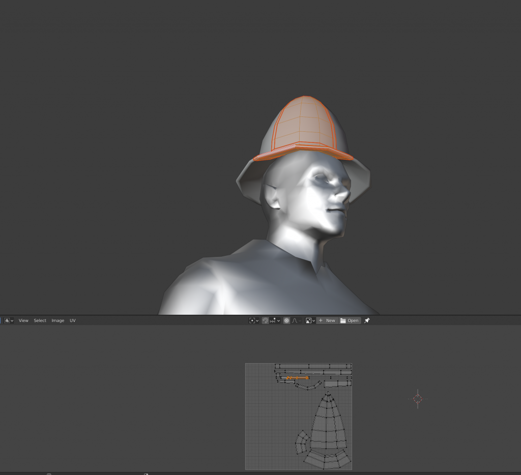
I personally don’t like this layout, and instead choose to utilize the lower screen. This can be expanded by grabbing its edge and dragging it up (as shown in the image bellow). Once it’s large enough, select the drop down menu, and select “UV Editor”. Again; I personally prefer this layout, but you should work with what’s comfortable for you.
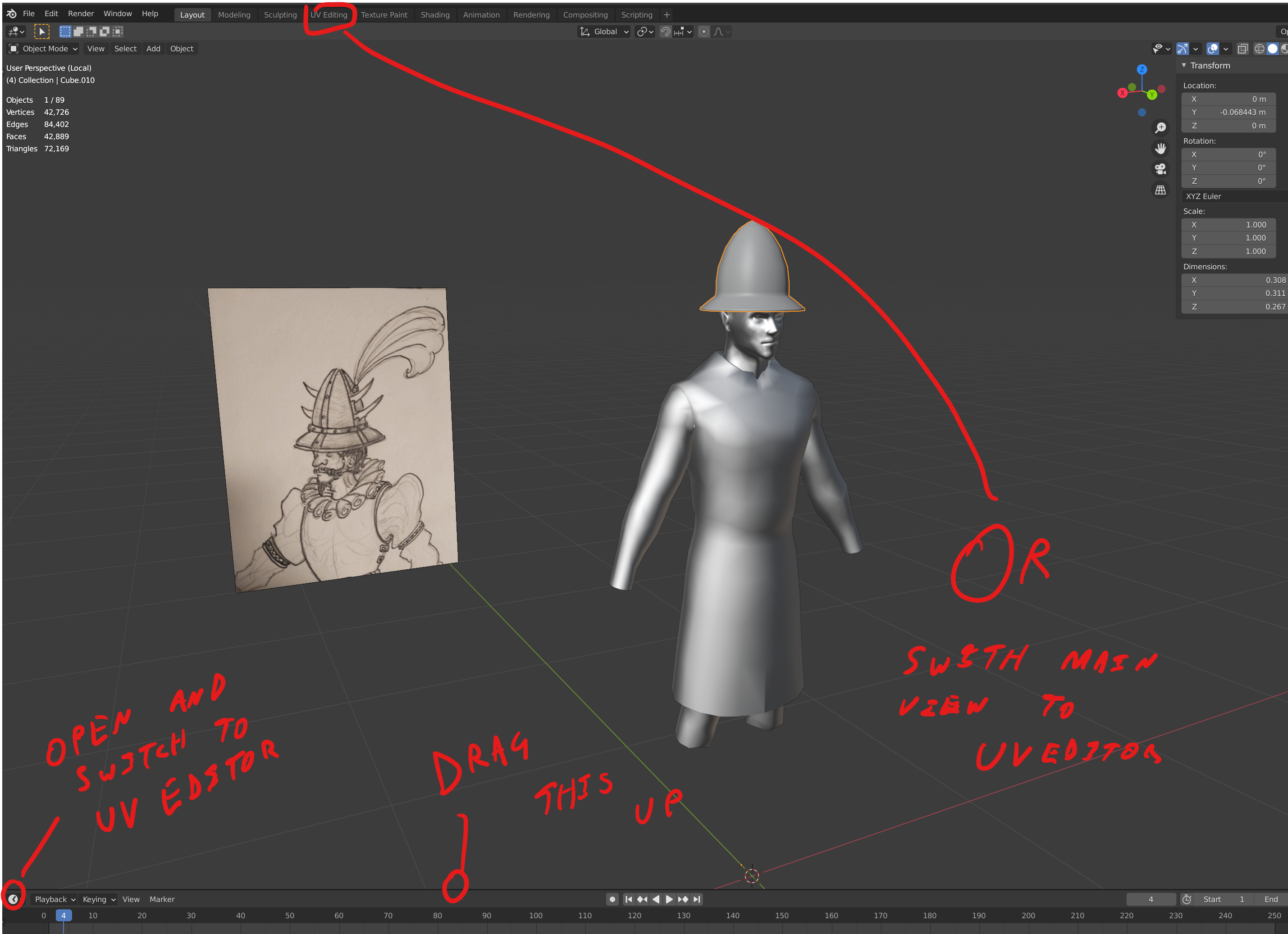
Two ways to access the UV Editor.
Once you have the UV editor open (whichever way that is), make sure you’re in edit mode, and select everything. It doesn’t explicitly matter if you’re in vertex, edge or face mode, but I find it easier to manage UV’s in Face mode myself.
Once you have everything selected, hit [U] on your keyboard. This will bring up the Unwrap menu. Don’t worry about all those other options right now. All you need is the topmost one labeled “Unwrap”.
Note how the clusters are fairly recognizable and distinct. This is thanks to the seam marks we made earlier. Without these, you may end up with more obtuse shapes to each ‘island’, which can not only result in distortions, but also make planning out your texture layouts harder.
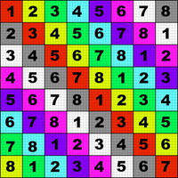
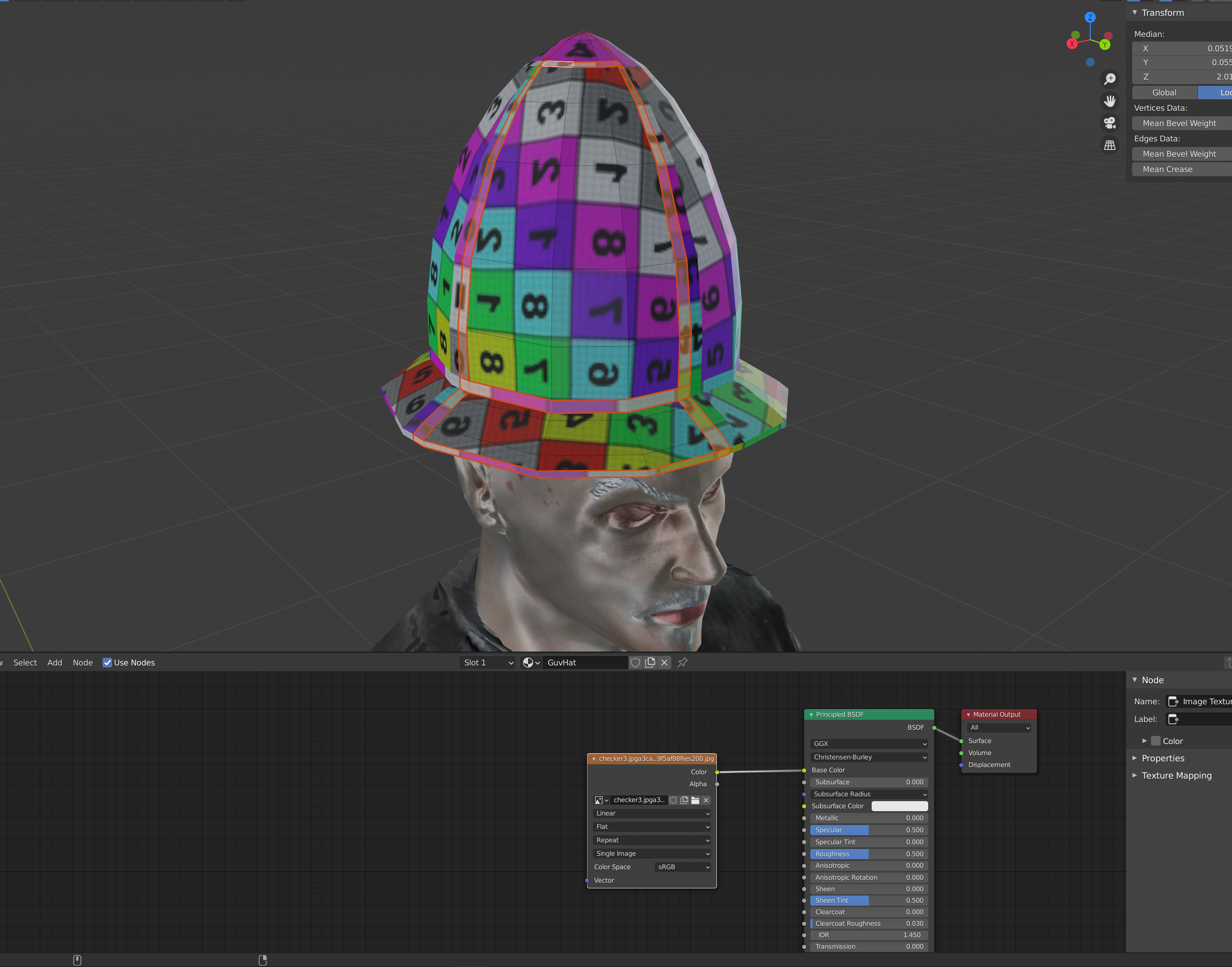
Speaking of distortions, we’ll need some help in making sure our layout doesn’t result in those. For that, we need to assign a temporary texture, one which has clear directions and size references. Checkered patterns are good for that, and in this case, I went with this wonderfully gaudy one.
Yes, it looks hideous, and yes, it will look even more hideous on the model. However, the patterns and details- such as they are- will help us make sure everything is showing up right.
But how do you actually get that – or any other texture- on the model?
Throwing some Shade(r)
First; set your Viewport Shading mode to “Material Preview”. If you don’t set that, or at set it to the more complex “Rendered”, nothing will change in your scene.
Next, head back to that drop down from where you accessed the UV Unwrap. As with accessing the UV Editor, there is a tab up above to jump directly, but the layout is likely to be even more chaotic for someone who is not used to 3D editors, so I don’t recommend it.
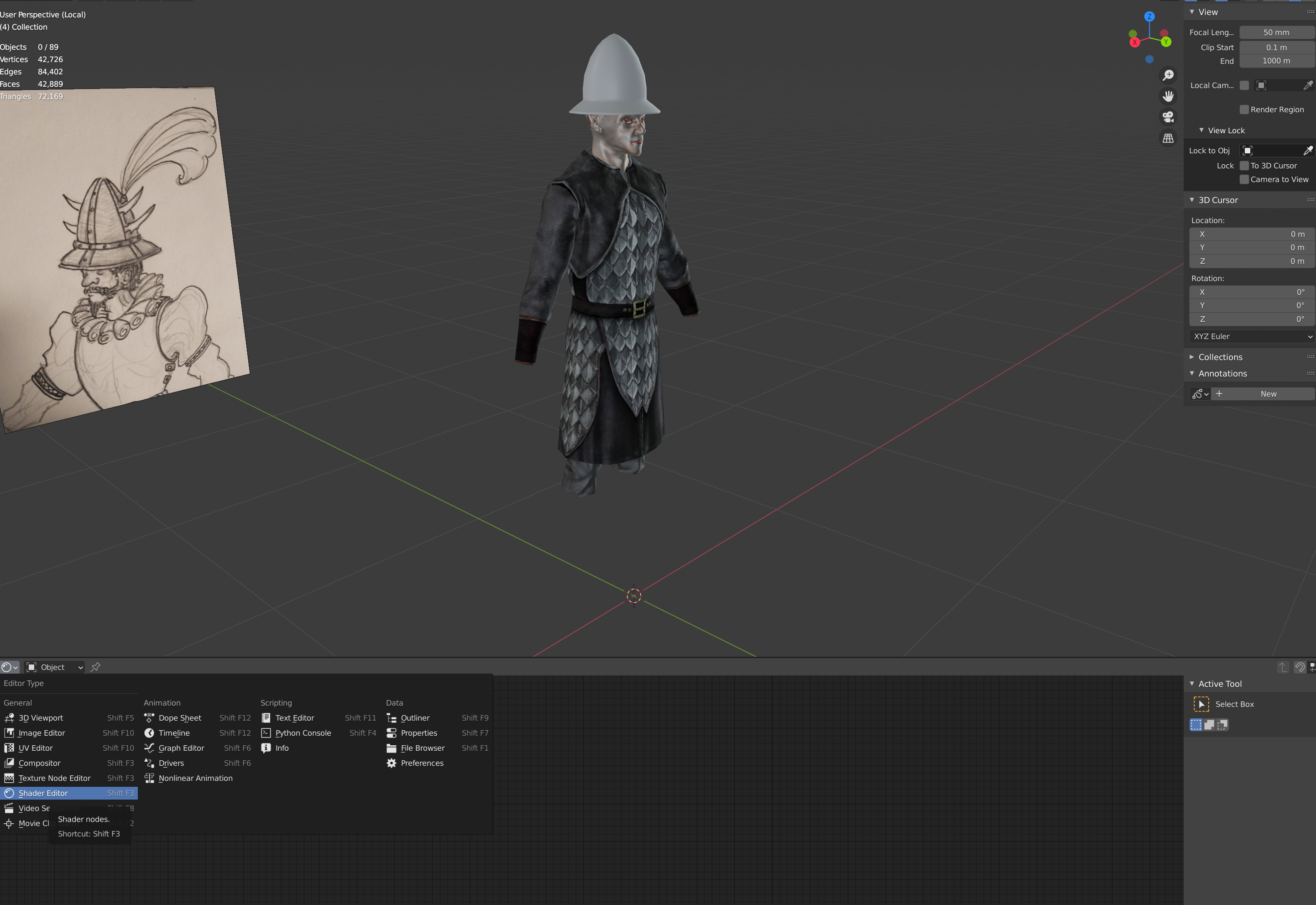
In any case, select the Shader Editor option form the drop down.
Now, one of two things might happen. Either you’ll see a whole lot of nothing, or you’ll see a confusing list of -things-. First, let’s address the “whole lot of nothing” option.
The page may appear empty because your object doesn’t have a Material assigned to it. Think of the Material as a box of all your posters, decals, and other 2D art pieces that will be layered on top of your mesh. It’s a collection of all those things that will give it detail, shine, and whatnot that have nothing to do with the geometry itself (aside from the UV unwrap).
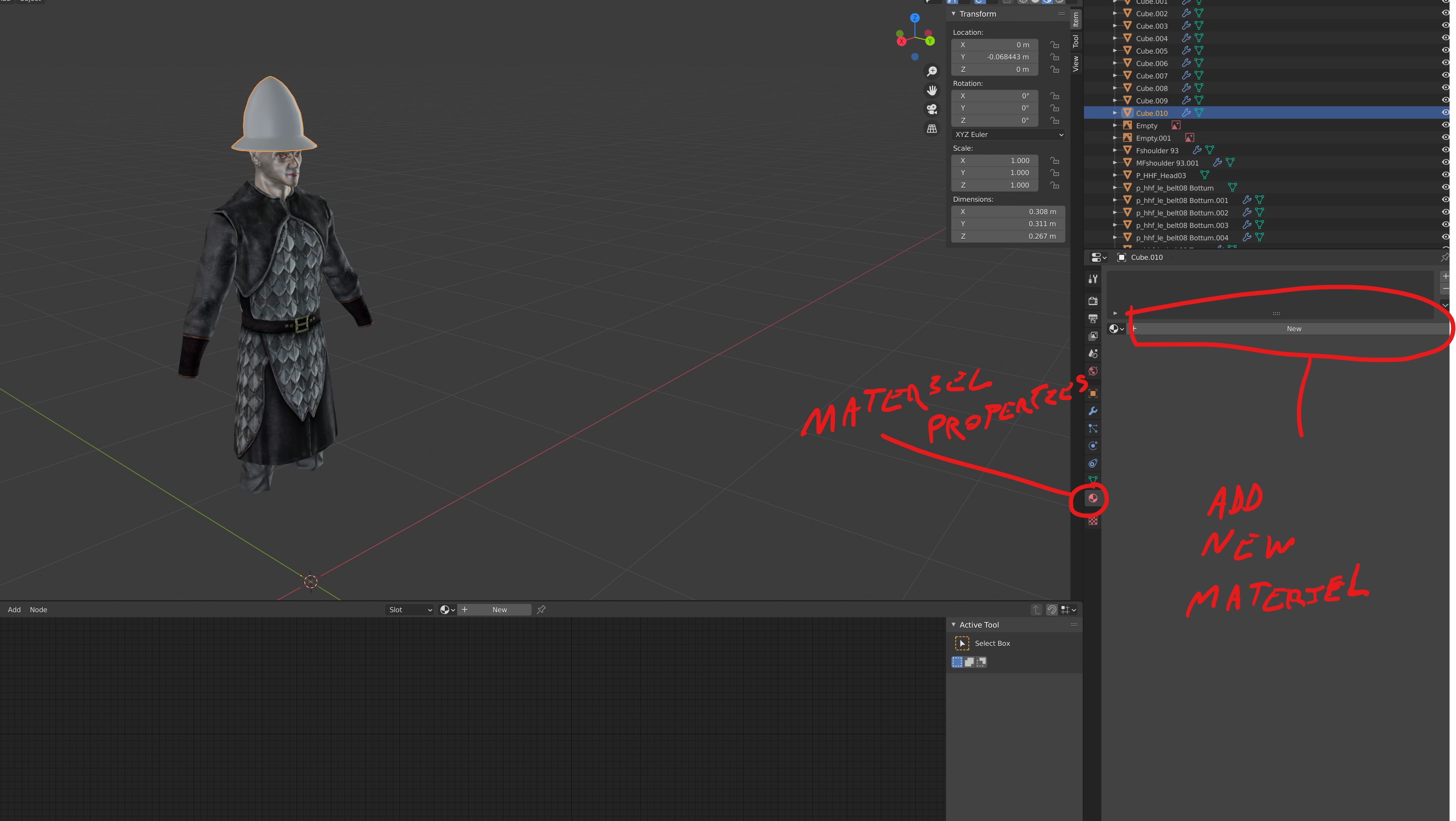 To assign a Material, first open up the Material Properties tab (as indicated in the screenshot). Then click on “New”. Immediately, you’ll see that slab of confusing -things- I mentioned earlier, appearing in your Shader Editor.
What you’re looking at is a list of all the properties and slots for your material. These slots can have image files, sub-shader functions, or other bits of data plugged into them to generate a specific result.
Most of these slots are of no concern for this project. The ones we will cover are the Base Color, Alpha, and Normal plugs. I will also cover Roughness, Metallness and Specular, though in truth, for a Neverwinter Nights 2 model, Metallness and Roughness are not especially important either. They are, however, good to understand for modelling work in general, and I find it easier to work with them and simplify the result from there.
Anyhow, the next step is to add a node. Specifically, an ‘Image Texture’ node. To do this, keep your mouse over the Shader Editor screen, and hit [Shift] + [A]. From the resulting menu, select “Texture” and then “Image Texture”. You should find the needful node, now following your mouse around in a similar manner to how a new mesh in the 3D view would. As in the 3D view, just left click anywhere to confirm placement.
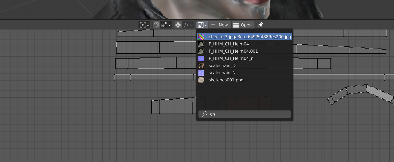
Once the node is down, click on “Open”, and look for the checker texture in question. (Or really, any texture you’ve decided to use for the time being).
And…. nothing happened! Tadah! Magic!
We still have to connect the node to one of those many slots. In this case, we want the texture to serve as our “Base color”. To do that, just drag a connection between the yellow dot (labeled ‘color’) on your newly created node, to the yellow dot on the main list labeled “Base Color.”.
In the interest of not having our motivation dashed by seeing the helm turned into a clowns hat, let’s hurry on to the next step!
Lay it all out
Switch back to your UV Editor. The first thing we want to do is start organizing our parts. That is, setting aside those parts of the model that should be a distinct material or color, and setting them in their own space of the canvas. Doing so will make the actual texturing work a little easier. To do so, we need to grab our “islands”, and move them around the image preview.
SELECTION IN THE UV EDITOR
As in the 3D view, there are a number of selection modes in the UV editor. In addition to the Vertex, Edge and Face selection modes (which function the same way as they do in the 3D view), you can also enable “island” selection ([4]), which will select all isolated shape clusters. For this stage of the tutorial, you will want to rely on it the most.
We’ll start with the islands we made for the brass rims, and move them all to the top right of our image.
Note that you can place two islands on top of each other. In some cases, this can be undesirable, but in others it can be immensely helpful. Note that you can scale, rotate, and flip your selected islands to better fit your texture or layout.
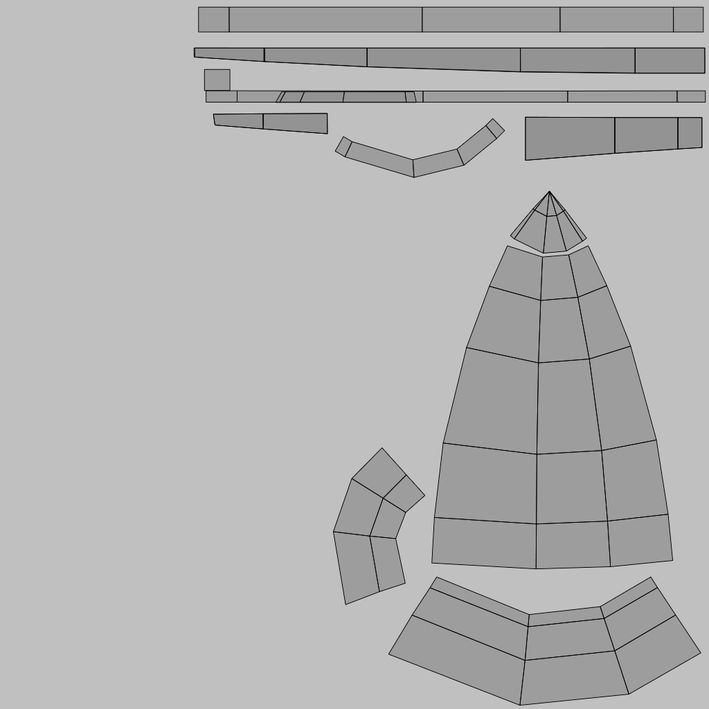
Try to organize your model’s UV unwrap to look something like the image bellow.
With that settled, we’ll get back to refining our helmets shape. Ah, but first! We need to make sure our faces (polygons) are facing in the right direction.
Showing Face
One thing to note about each individual polygon is that they are one-sided. That is, they have no back. When you see a back in Blender, it’s mostly a little bit of assistance for you to keep track of things. If you were to render the scene, or take the same mesh and put it in a game, you would find an invisible surface behind each polygon.
So, how do you tell which way your poly’s are facing?
There are a few ways to do this, some of which are dependent on your Viewport Shading Mode.
If you are in Solid Viewport Shading, click on the drop down icon on the right of each option, as indicated in the image. From the resulting menu, look for “Backface Culling”, and check the box.
If you are in Material Preview Mode, however, this option is nowhere to be found. Instead, you will need to over to your material properties tab (the same one we visited to create the material in the first place). Once there, scroll down to “Settings”, and look for the “Backface Culling” checkbox.
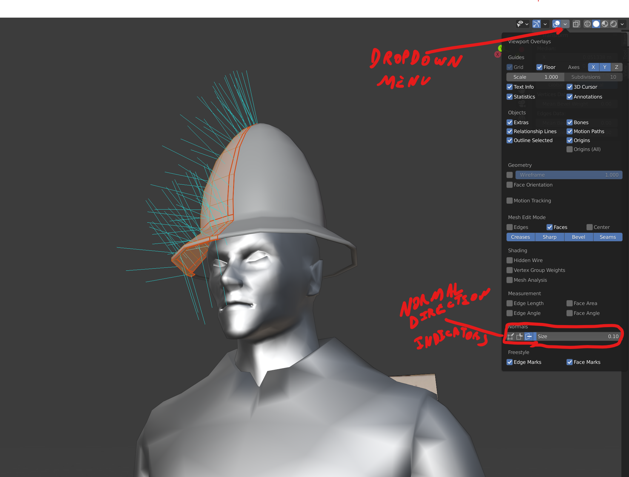 The third option is unlikely to be terribly useful to you if you’re just starting out with Blender, but is quite handy in some circumstances. While you’re in Edit Mode, in the same line of icons, find the drop down on the -left- this time (Viewport mode doesn’t matter). This list is slightly larger, but you only need to find the Normal’s options near the bottom. These options will each draw out a line moving in the direction of the “normal” (Face/ direction) of the edge, vertex or polygon, depending on which option you engage. You can also adjust the size of these lines.
For the purposes of this tutorial, just use the Material Setting option.
A final note on the ‘Normal Direction’; if you find that all your 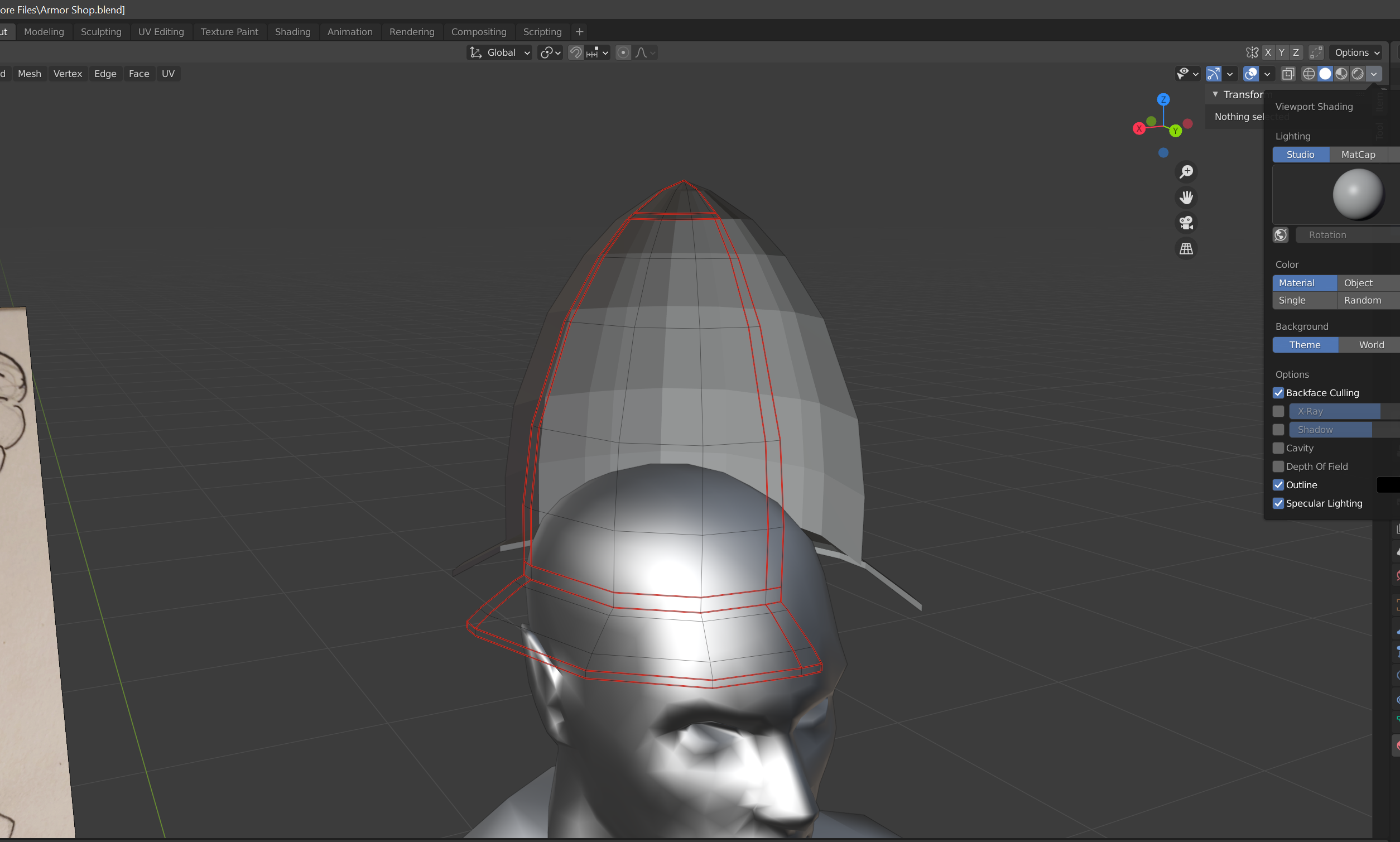 poly’s are facing in the opposite direction (as per the example here), don’t panic; this is easy enough to fix.
First, select all your poly’s ([A]) while in Edit Mode. Then, click on the drop down menu labeled “Mesh”, and head down to “Normals”.
SHORT CUT: [Alt] + [N]
The option you want in here is “Flip”. “Recalculate Outside” can also work in some cases, but right now we just need to flip the direction.

The Under-layer
Take a moment to assess your shape, and make any position adjustments you need. Don’t worry if the shape still looks a little bit blocky, we’ll solve that in a bit.
When you’re done with those adjustments, the next step will be to form the underside of the helmet. We only need a small part of it, and don’t need the entire dome to have an interior. After all, it will never be seen in game.
Copy the faces as indicated in the image by selecting them, and hitting [Shift] + [D] on your keyboard.
As with all creation commands, you will need to either left click to confirm, or right click (to confirm and cancel all movement shifts).
Once the copy has been created, hit [Alt]+[S] again, and shrink down the selection till it looks something like this.
While we’re at it, flip the selected Face’s direction via the same steps we used before to make everything face outward. Only in this case, we want the faces to point inward. Again, all you need to do is hit [Alt]+[N]. and select “Flip”.
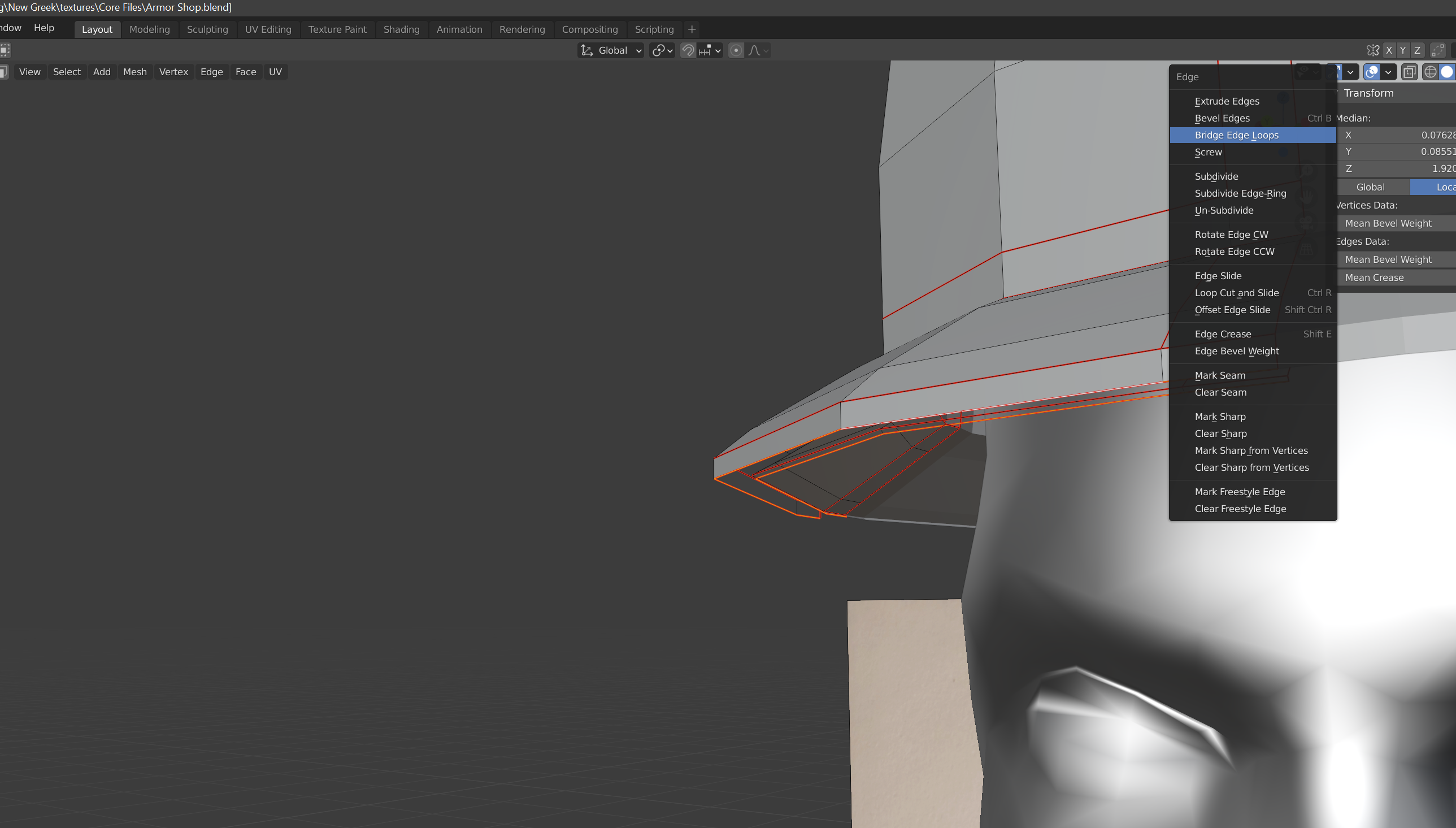
Next up; we need to connect the two sides (in and out) from the base. To do so, select the lowest edge loops of both the main shape and the new inner-lining. Then, hit [Ctrl]+[E] to bring up the Edge Context menu (Or just click the right mouse button, if you’re already in Edge Selection mode). Finally, select “Bridge Edge Loops”.
It looks like there’s a bit of a gap between the inside of the helmet, and the scalp of our mannequin. That’s 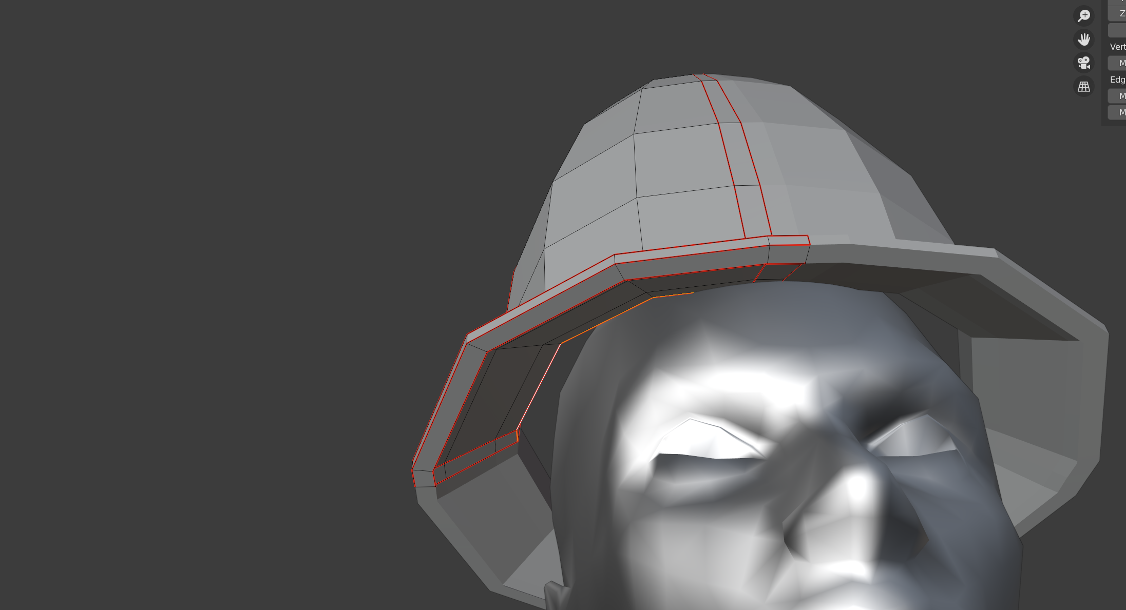 fairly easy to fix with the Shrink option we used before, so go ahead and select your topmost loop of the inside, and shrink it down till it’s touching the head. It’s okay if it goes a little further inside.
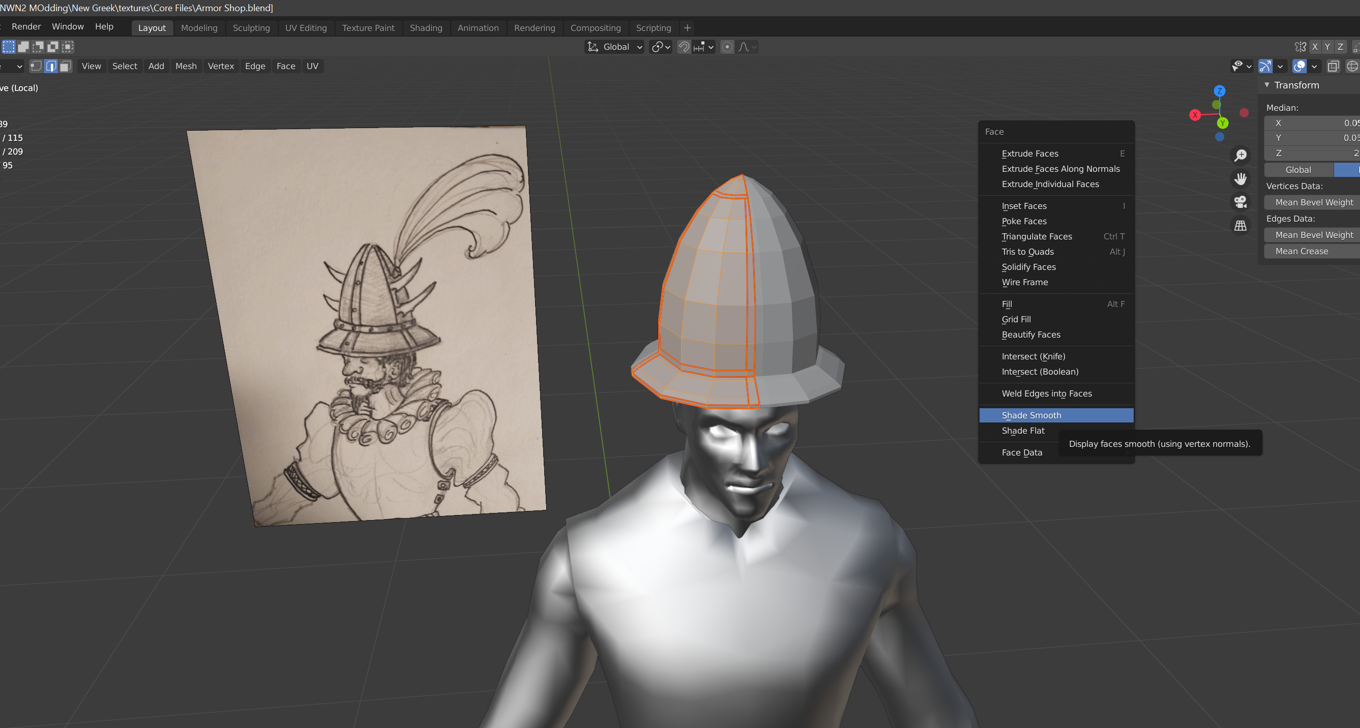 Now would be a good time to deal with the boxy look of the helmet. Select all faces, and either press [Ctrl] + [F], or click the right mouse button while in Face selection mode, to bring up the Face Context Menu. Then select the “Shade Smooth” option.
Assess and Refine
Take a moment to look over your mesh, and make any adjustments to the shape you deem necessary.
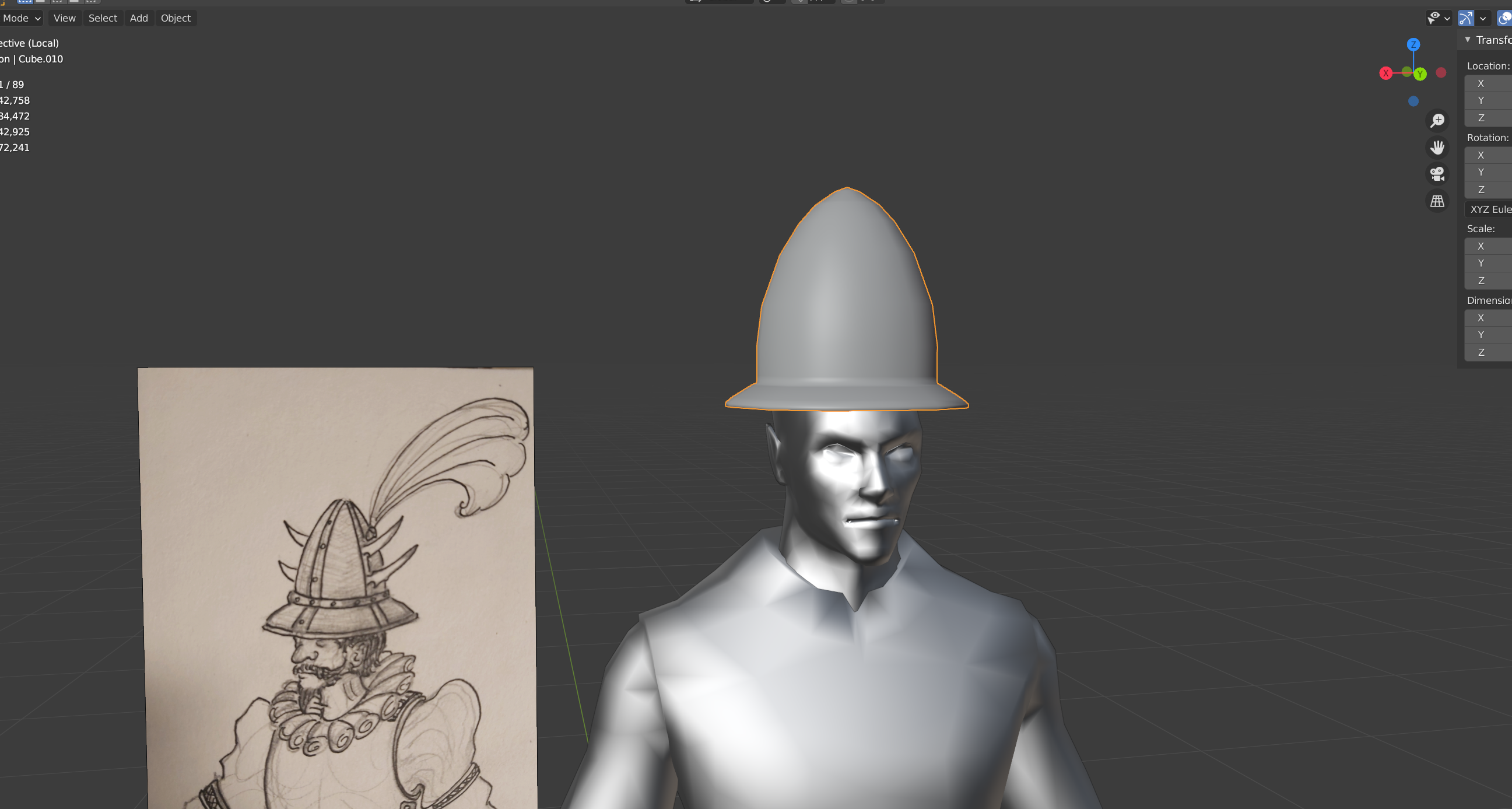
Once the most visible parts are where you want, turn back to the underside. Since it’s a direct copy of the top, it will have the same number of edge loops as above. This is not necessary, as it doesn’t need to be as smooth, nor does it need that number of polygons. As noted in part one of this series, the number of polygons does matter, so we’ll want to keep that as low as possible without sacrificing our overall look.
We can get rid of edges, faces, and even vertex’s fairly easily, without making too much of a mess. In this case, select the two middle edge loops on the underside, then hit [X] to bring up the Delete menu. Next, select “Dissolve Edges”. The result will intelligently delete the selected edges and vertex, while attempting to keep the shape and as much of the UV as possible. This is handy when trying to make minor reductions in the polycount at the end of the modelling process, since the more often used Decimate modifier can be a little messier.
The Decimate Modifier
The Decimate modifier is used to reduce the total number of faces on a model all at once. It’s good if you’re trying to bring a very, very detailed object down, but be careful with it! It can cause odd warping issues in the UV, and not necessarily keep your shapes just so. Handy tool, but don’t rely exclusively on it.
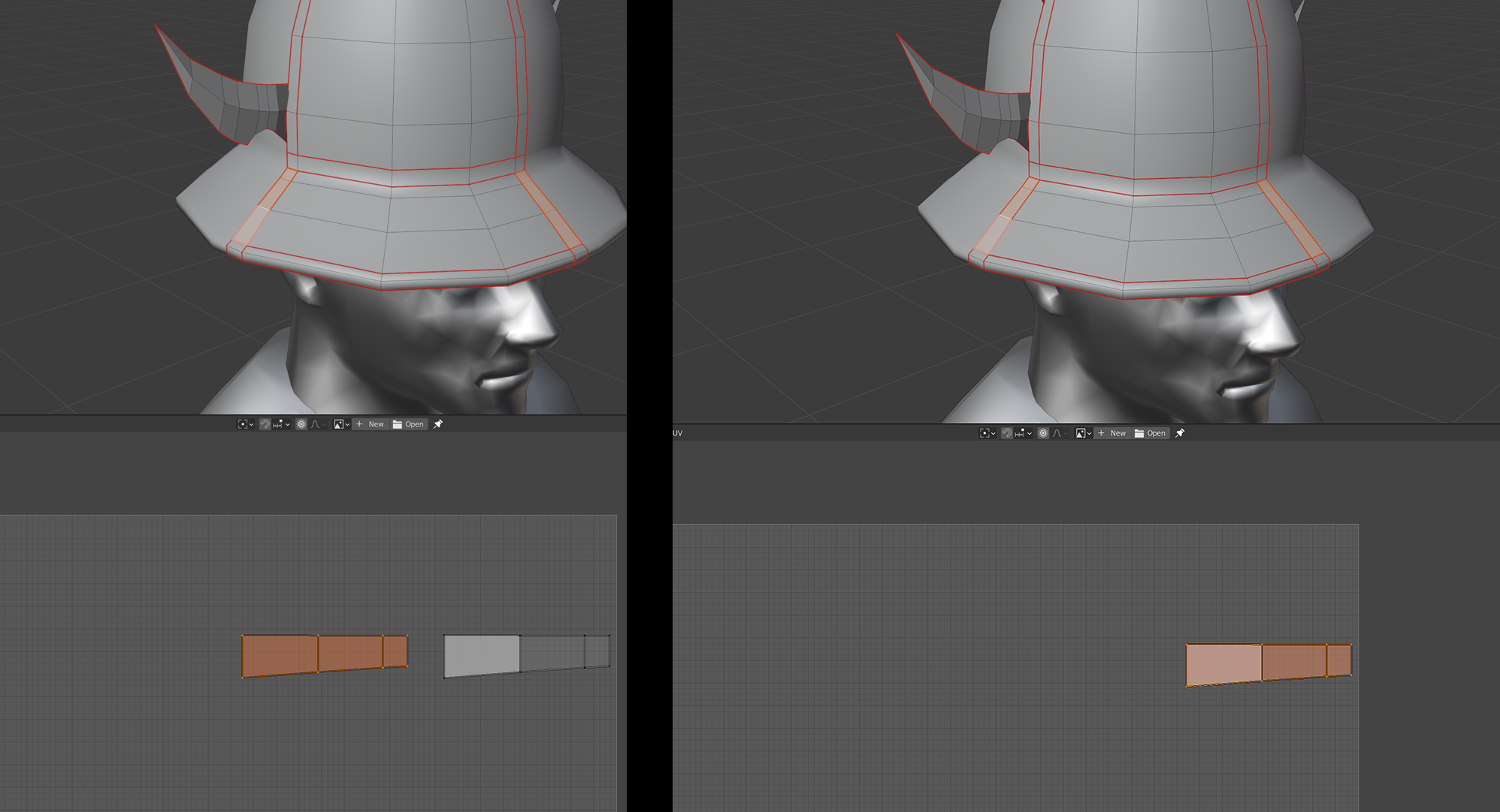
Even though our Dissolve Edge function will not likely have effected the UV too drastically, we do need to revisit the unwrap, and redo a few things. Go back to your UV Editor, and organize your layout till it looks something like this. Remember; you can have parts of your UV overlap if you want them to look identical to each other, when the texture is applied. Use the checker texture from before to identify and iron out any warping issues.
 Make it Edgy!

With the main helm itself mostly (but not quite) done, we can move on to some of the accenting details. Let’s start with the blades.
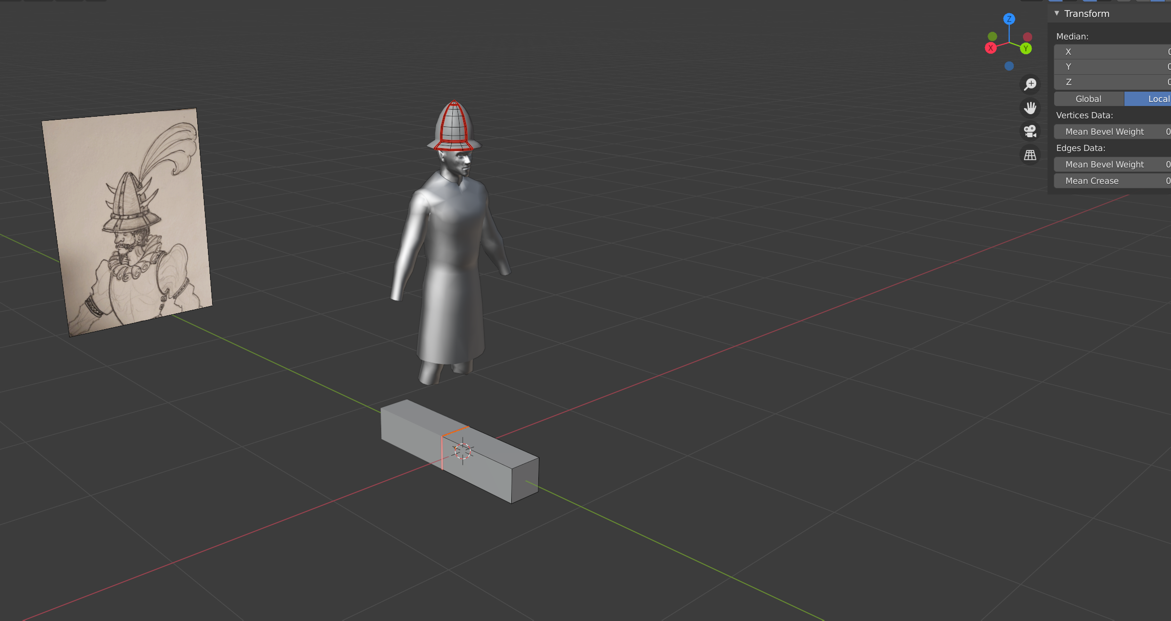
First (while in Edit Mode), bri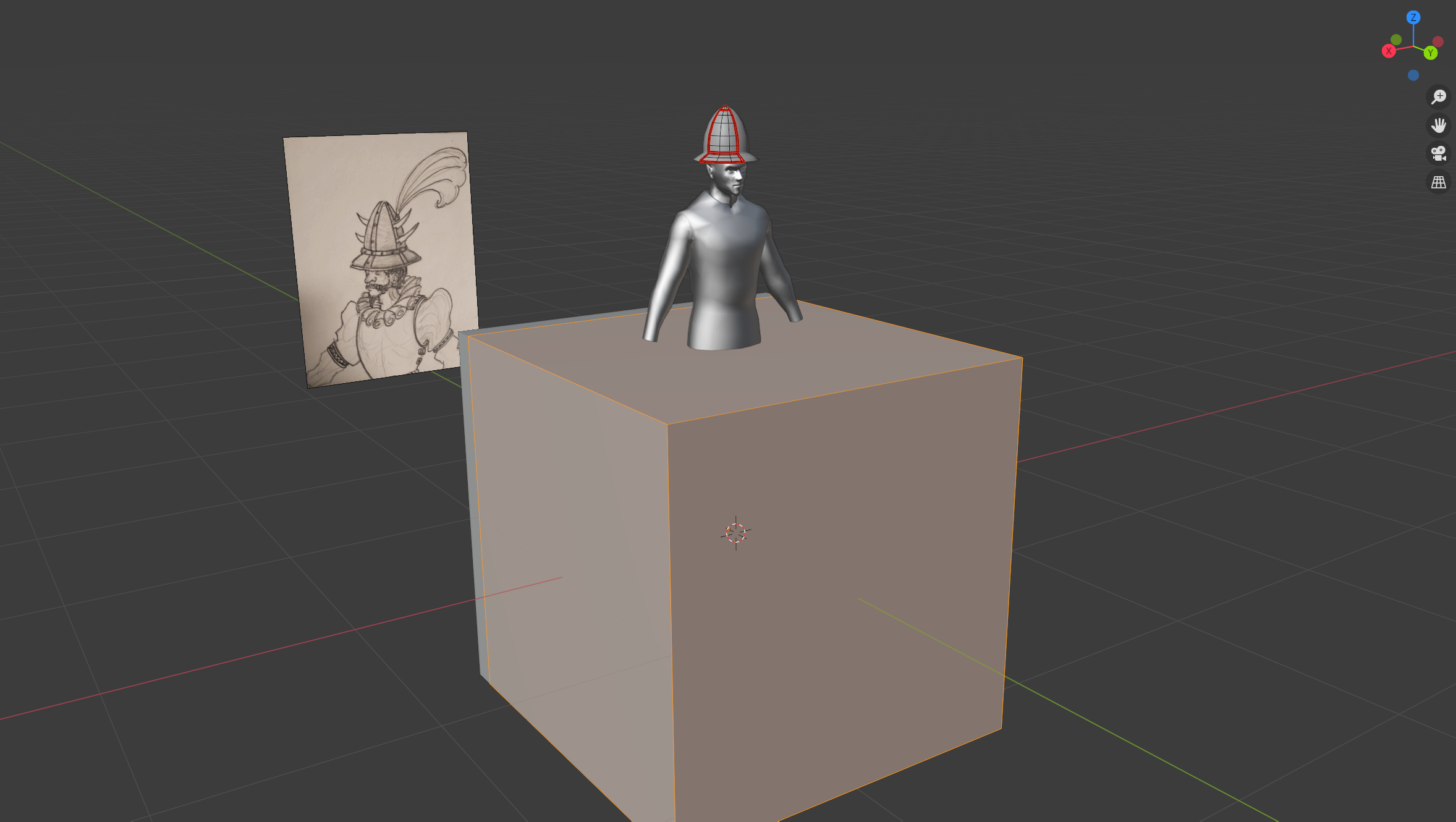 ng up the Add Mesh menu by hitting [Shift] + [A], and select “Cube”.
 Make an edge loop running along the X axis, and mark it as a seem. Select all shapes on one half of the seam line (preferably the ones running behind the body), and delete them. As you’ll notice, our Mirror modifier is still in effect, which means the mesh will still be reflected, even after we delete those faces. This is by design, so don’t worry about it.
Shrink the box down some more, and then flatten it a little on the Y axis (but not all the way, we want some breadth to it).
Once it’s flattened, select the whole cube (but make sure nothing of the hat itself is selected), and bring up the Separate menu by hitting [P] on your keyboard. Click on “Selection”. This will separate the selected surface from the helmet mesh, but keep its assigned Material and Modifiers. In a few steps, we will re-attach this piece, but it will be easier to shape it without the helmet proper being editable.
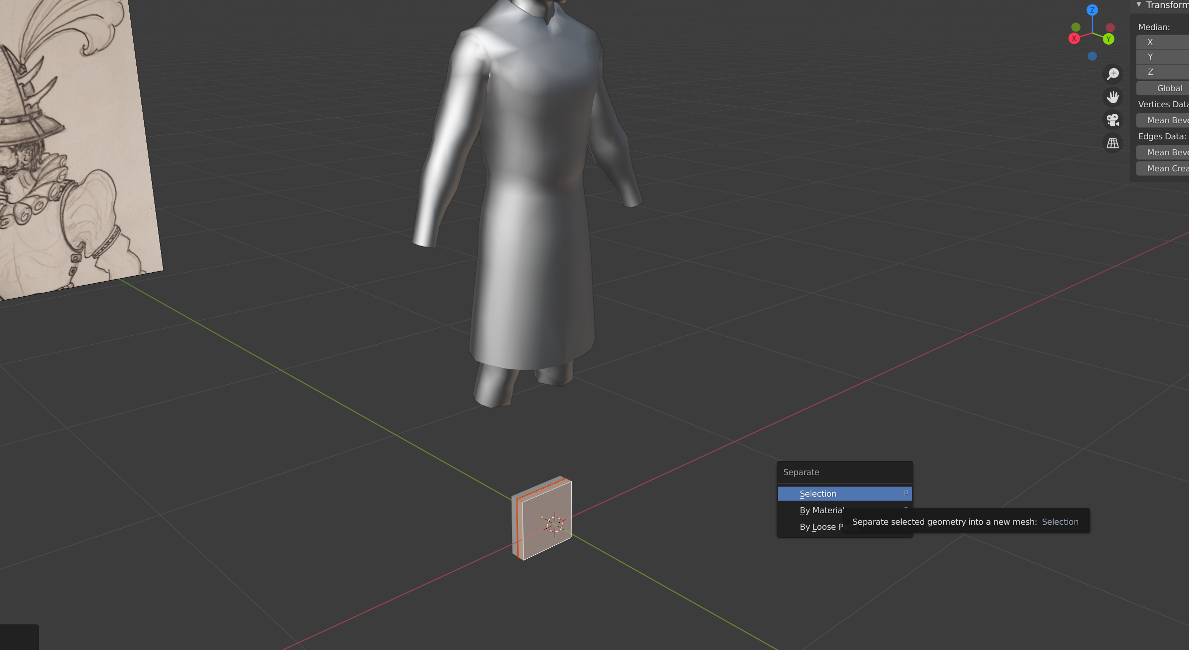
Note that once this box is separated, it’s edges, vertices and faces can no longer be selected. It is now regarded as distinct from the mesh it was initially created in, and we are still in edit mode for that latter shape. To switch out, just exit Edit Mode by hitting [Tab] as before. Left click on our ‘new’ mesh (the box), and hit [Tab] again to re-enter Edit Mode, only this time for the box instead of the helm.
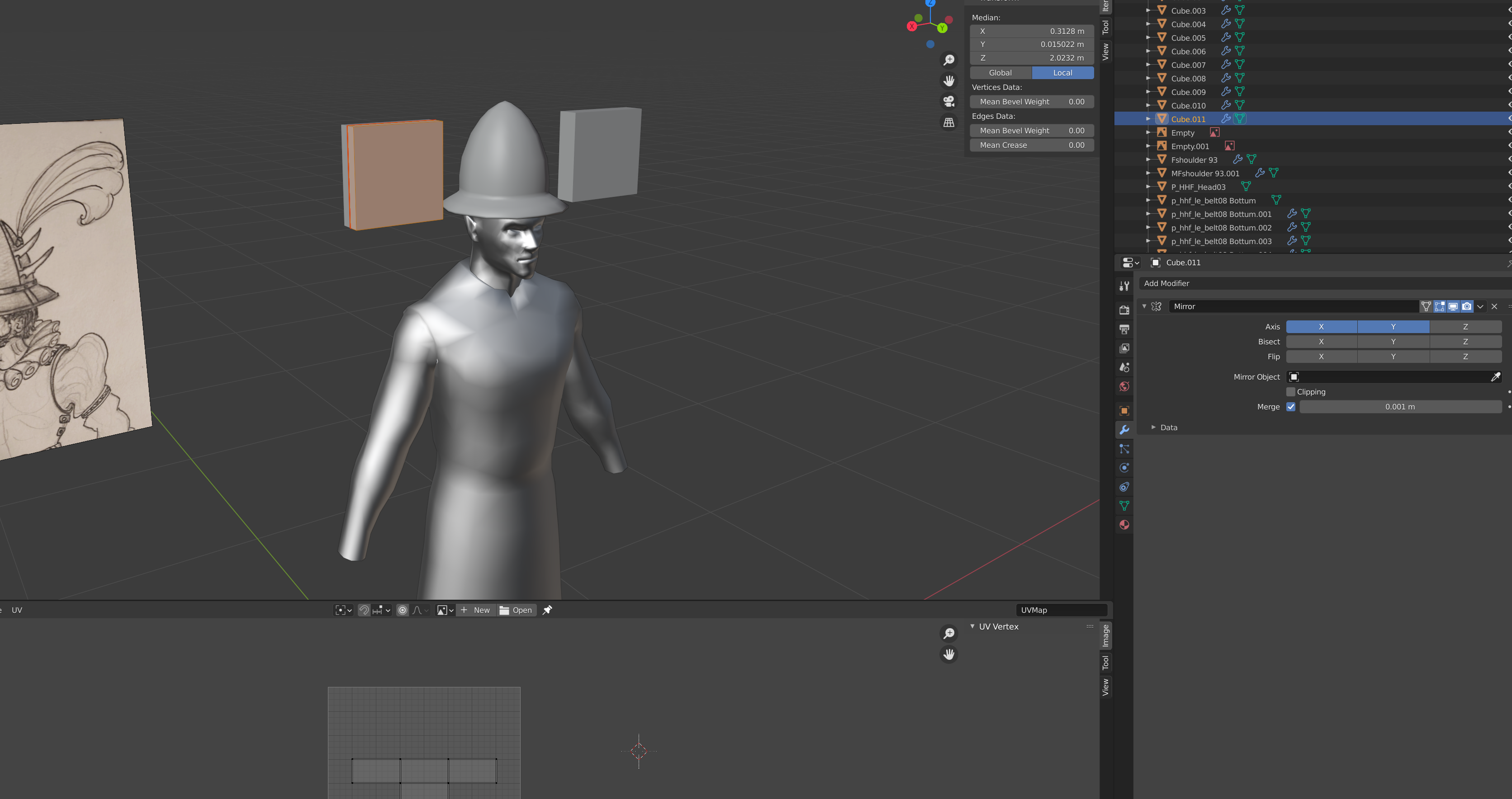
Select all parts of the mesh and move it up on the Z axis till it’s near the middle of the helmet dome. Then, move it on the X axis, so the mesh is all visible. Notice that the Mirror modifier is still reflecting it on the X axis, which means we see a clone mounting on the opposite end. As with the main helmet, make sure the marked seam is both scaled at Y to 0, and that it’s Y transform position is 0. Push the further face inward a little till to give it a flatter profile.
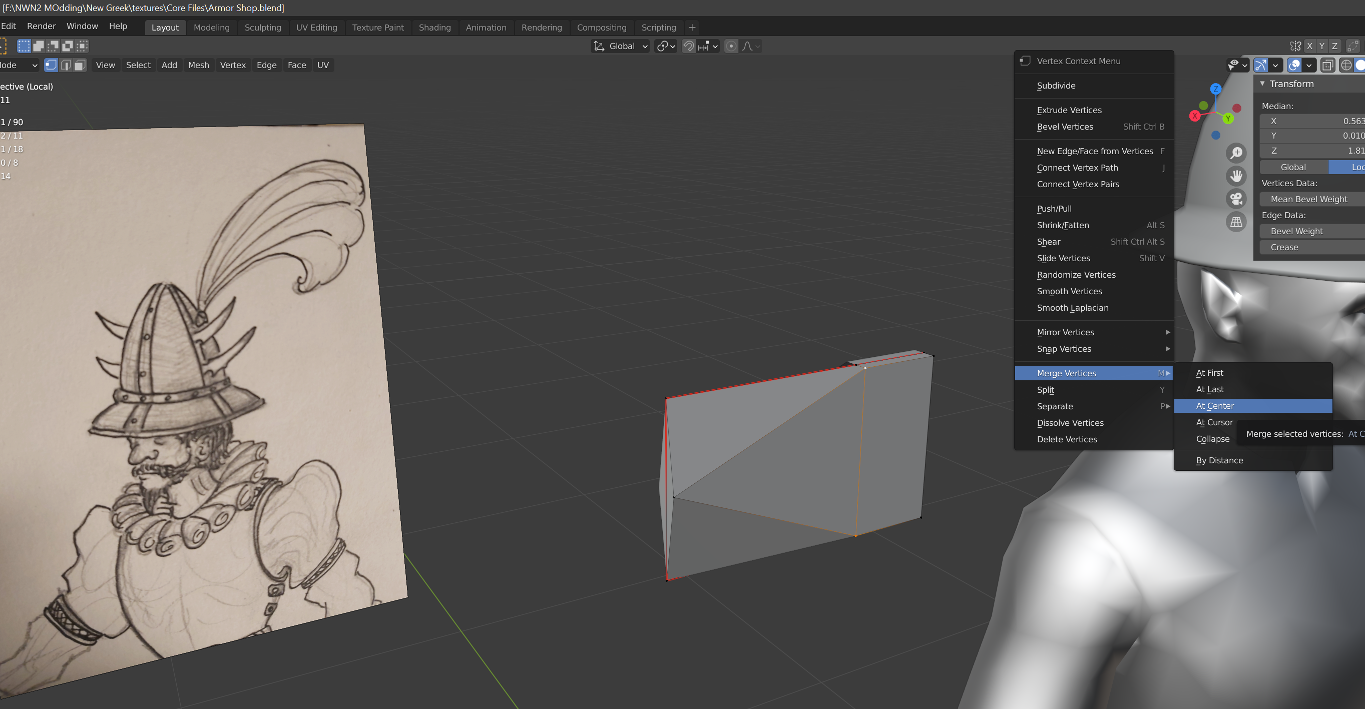
Before shaping up the blade, we need to work on its cross-section, so it’s less of a box and more of a diamond. For that, we’ll merge the top and bottom vertices with each other, as shown bellow. You specifically want to either collapse or hit “merge at center”. Both will have the same result in this case.
Add some more edge loops either manually or by beveling an existing loop. Rotate, scale and move each one to begin defining the curve of the blade. Merge the three vertices at the tip of the blade to form a point, and make sure this new singular point is at Y transform of 0.
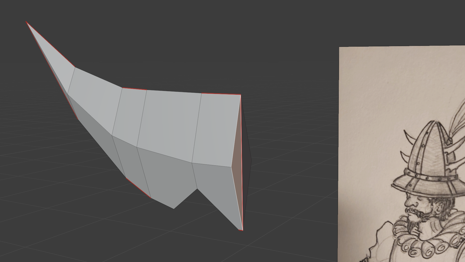
By the end of it, you want to land up with something like this:
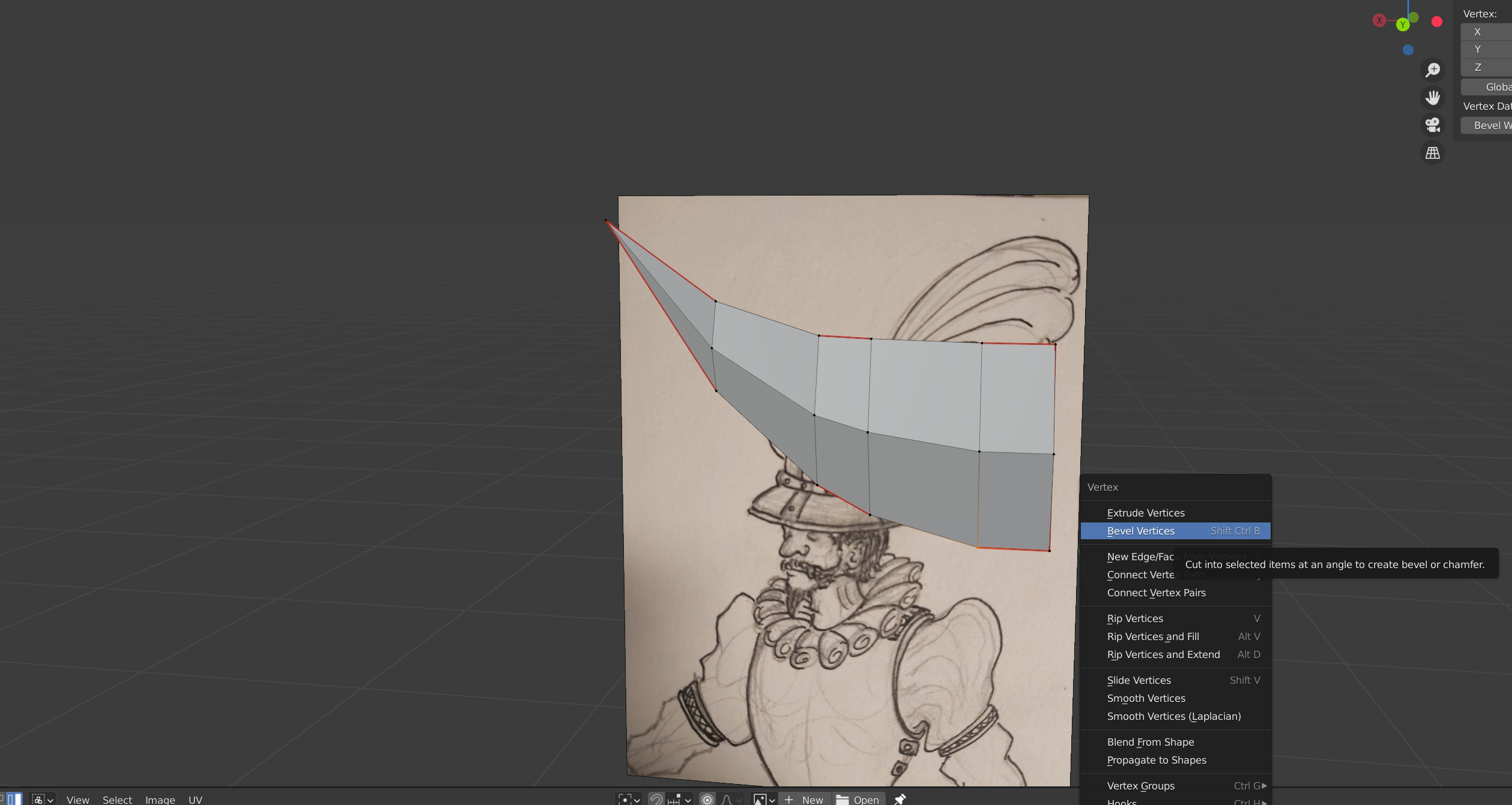
As indicated in the image, select the vertex on the second loop’s base, and bring up the Vertex menu by either right clicking, or hitting [Ctrl] + [V]. Select “Bevel Vertices”. This will give us the inner curve seen in the concept. For more fine control over the curve (and so it doesn’t so quickly run against other vertices), set the width type to “Percentage” in the confirmation window, then adjust the value accordingly.
Now select the newly created face (should be a triangle), and delete it, so that there is now a gap, forming our indentation.
go ahead and delete the faces behind the blade as well, as shown in the shot.
Select the edges forming the now empty triangle, and press [E] to start extruding. Lock the direction to the Y access ( [Y] key), and pull the new faces to the back.
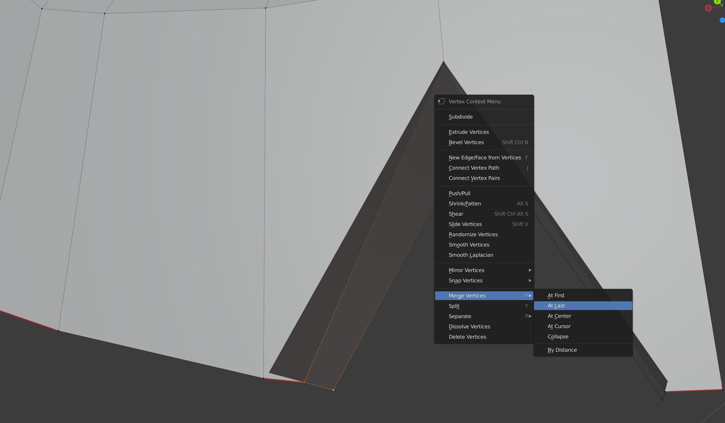
Now, select the vertex the new vertex on the base first, then the one that is still in line with the rest of the blade. Bring up the Vertex menu again, and select “Merge at Last”. Do the same for the two vertices on the opposite end.
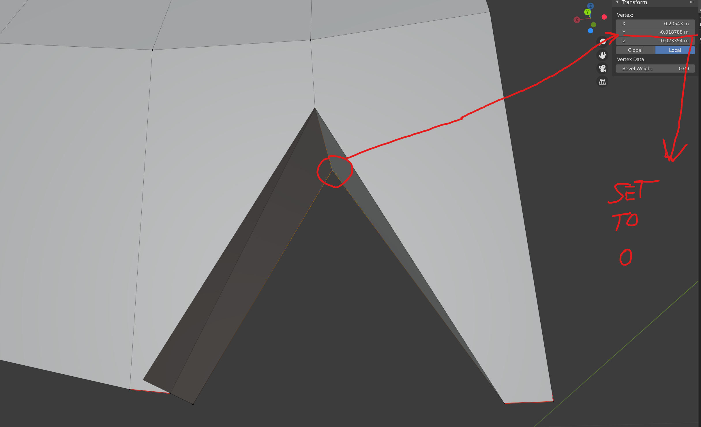
After that, select the newer vertex at the top of the triangle, and set its Y transform to 0.
Select the edge loop at the tip of our triangle, and bevel it to create a less angular, more curved form. On the confirmation window, feel free to add segments for a smoother curve.
Finally, select the whole edge loop running along the middle of the blades cross-section, and ensure it is 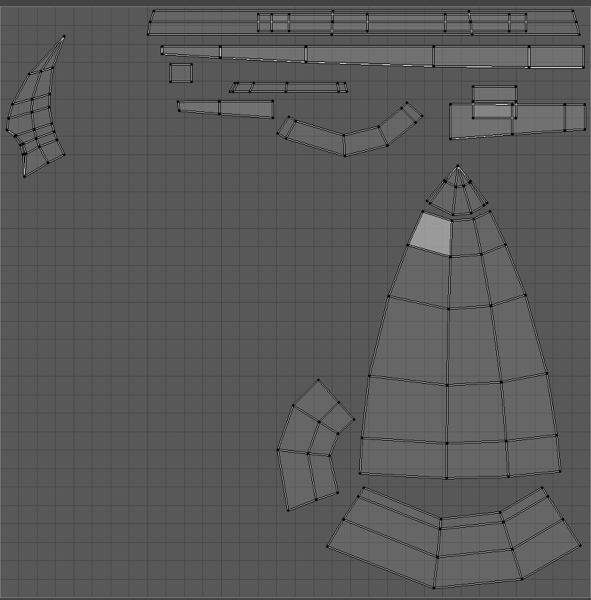 marked as a seam line, before selecting all faces and unwrapping them the way we did for the helmet. Once you do that, head back to the UV Editor, and move the blade’s UV’s to the top left of the canvas. You should land up with something like the next image for your UV layout.
Now all you need to do is size and orient the blades. Select all faces, and move them up and to the left, till the whole thing is roughly where it needs to be on the side of the helmet. Rotate and scale as needed, and if you scale, make sure to re-align the seam line,
Once it’s in position (and while still having the whole thing selected), you’ll want to clone it for the second blade. To do so, hit [Shift] + [D], which will clone all selected surfaces. Before you click to confirm, press [Z] to lock the transform access to up and down, then simply move the mouse till your new blade is roughly at the correct height level. Left click to confirm placement, and once again, rotate and scale as needed.
With the blades now properly shaped and positioned, it’s time to fuse them back on to the helmet proper. Exit Edit Mode, select both the blades and helmet ([Shift] + Left Click), then hit [Ctrl] + [J] to join them.
Send it to the (Photo)shop
The only modelling work left now will be adjustments to perfect the overall shape, and work on the plumes. Neither of these steps will be especially complicated, and are better tended to once we at least have the basics of our real textures going.
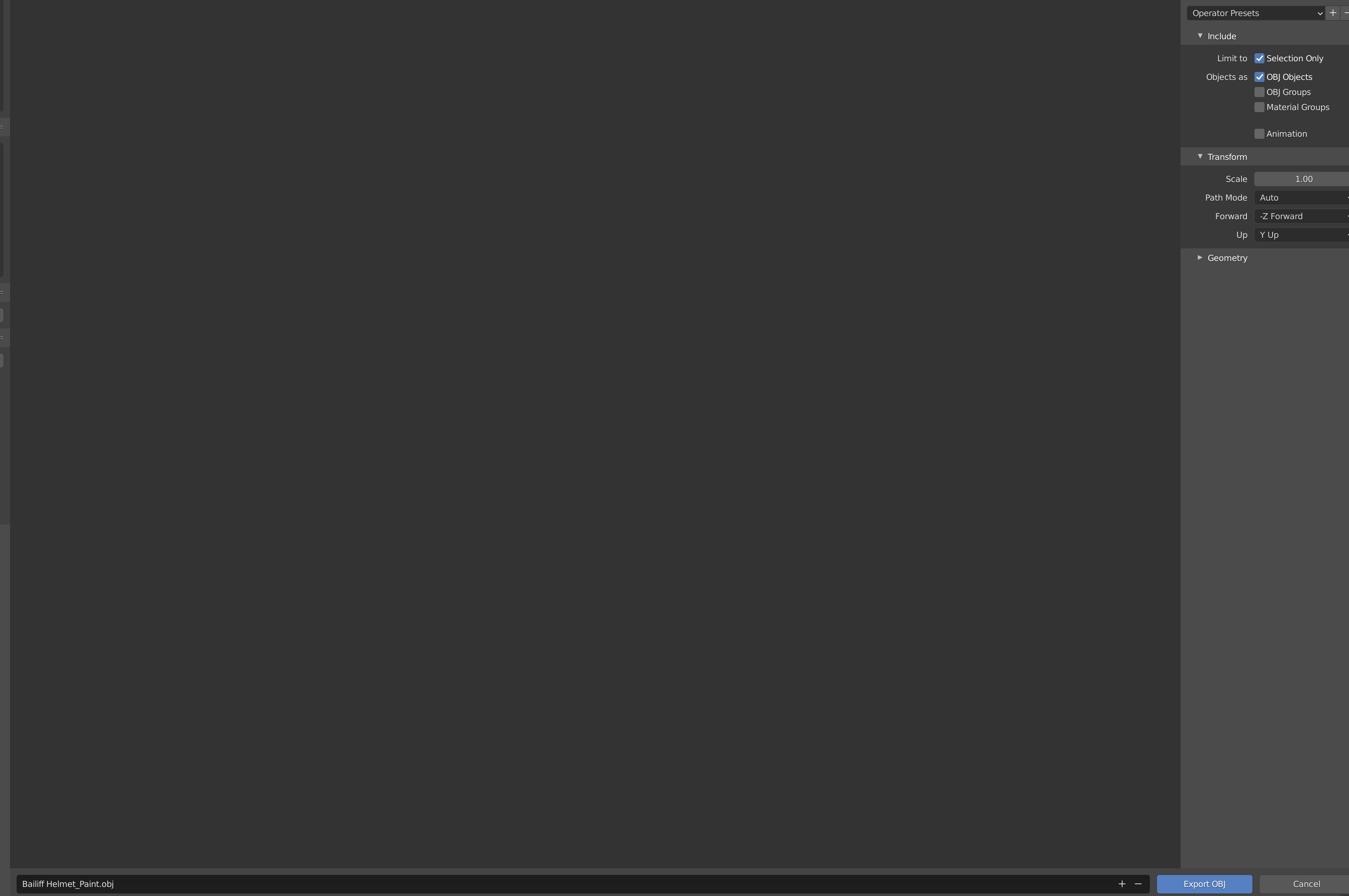
Blender does have its own texture creation and editing tools, but I am not personally as familiar with them as I am with Adobe Photoshop. Therefor, for the purposes of this tutorial, we are going to export our helmet to the ‘.OBJ’ format, which we can then load up in the aforementioned program.
To do so, make sure you have the helmet selected, then navigate to ‘File- > Export -> Wavefront (.obj)’. You’ll have a standard file saving window come up. Obviously, your name and directory matter only so far as you can easily find the file. However, what you do want to do is make sure the export is set to “Export selected”, otherwise you’ll have everything from the hat to the body and reference image going out with it.
Before we’re done in Blender for now, it may also be a good idea to make a copy of the UV layout, since current versions of Photoshop are a little bit odd about displaying UV’s correctly. To do so, g back into Edit Mode with your helmet selected, and return to the UV editor. Make sure everything is selected, and then navigate through “UV- > Export UV layout’. Save this as a PNG. Having this as a guide for your texturing will be handy, especially if you do not have Photoshop or are unable to use its 3D painting features.
Break Time!
This is likely a lot to take in if you’re new to modelling, so we’ll save the next parts for another post. The next steps will cover some basics on texture painting in Photoshop, though we’ll spend considerably less time there, as painting is kind of its own kettle of fish. Or other things. Why fish? Who knows…
Be First to Comment